Project managers who are responsible for developing competitive marketing strategies, know that having a good idea is not nearly as important as presenting that idea effectively to potential clients.
Quick and Simple Graphic Information
As a new communications tool, many companies have learned that SketchUp is uniquely suited to produce the kind of graphic information that is often critical to explaining a particular approach to a construction contract. Exploring this communicative potential and staying out in front of its power is essential in today’s competitive markets.
In fact, each of our construction modeling books ( http://insitebuilders.com) is a research project intended to both explain and explore not only the practical potential of construction modeling, but also to illustrate alternate ways to deliver and transfer construction information.
Presenting Construction Concepts
At the same time, constructors building 3D construction models for their projects also know that almost any model can be quickly cut and pasted from in-house libraries of previous projects. Once a construction model is ready for distribution:
Screenshots can be exported to illustrate a written proposal.
Sequence animations can be embedded into presentation programs.
Both the images and animations can be posted to the web.
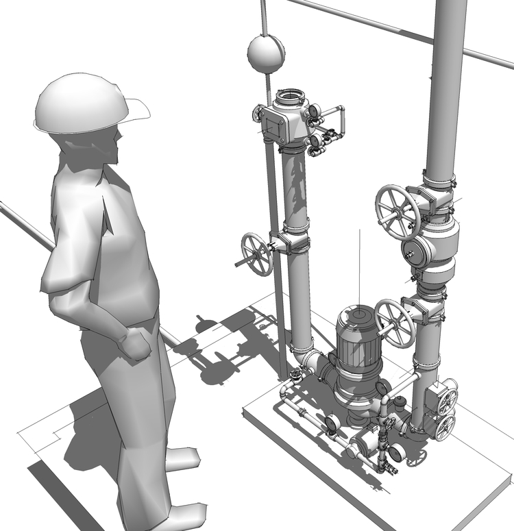
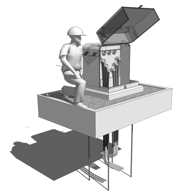
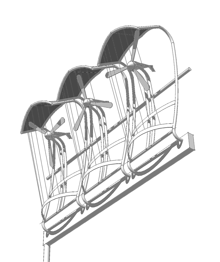
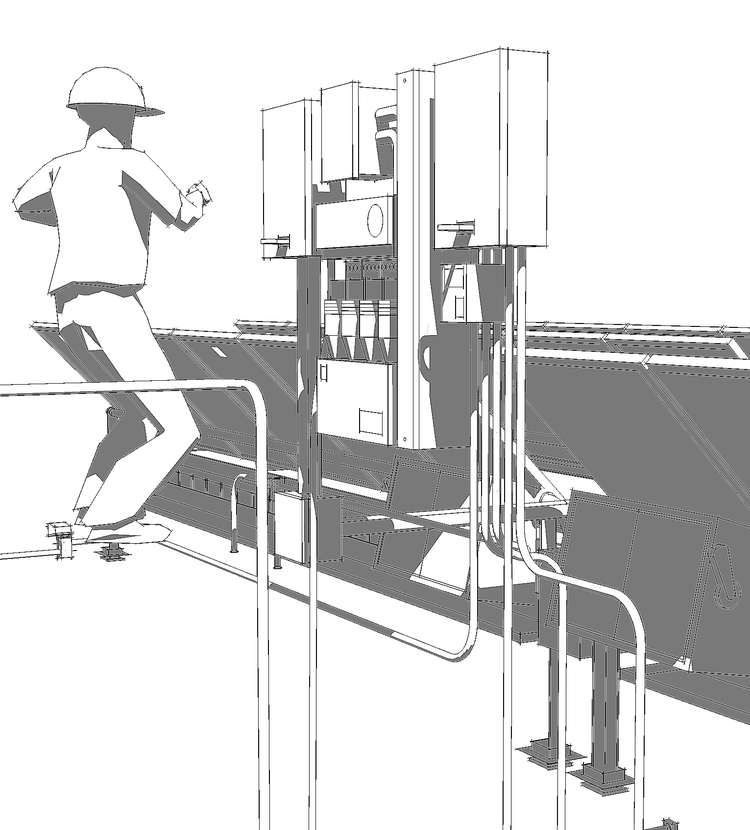
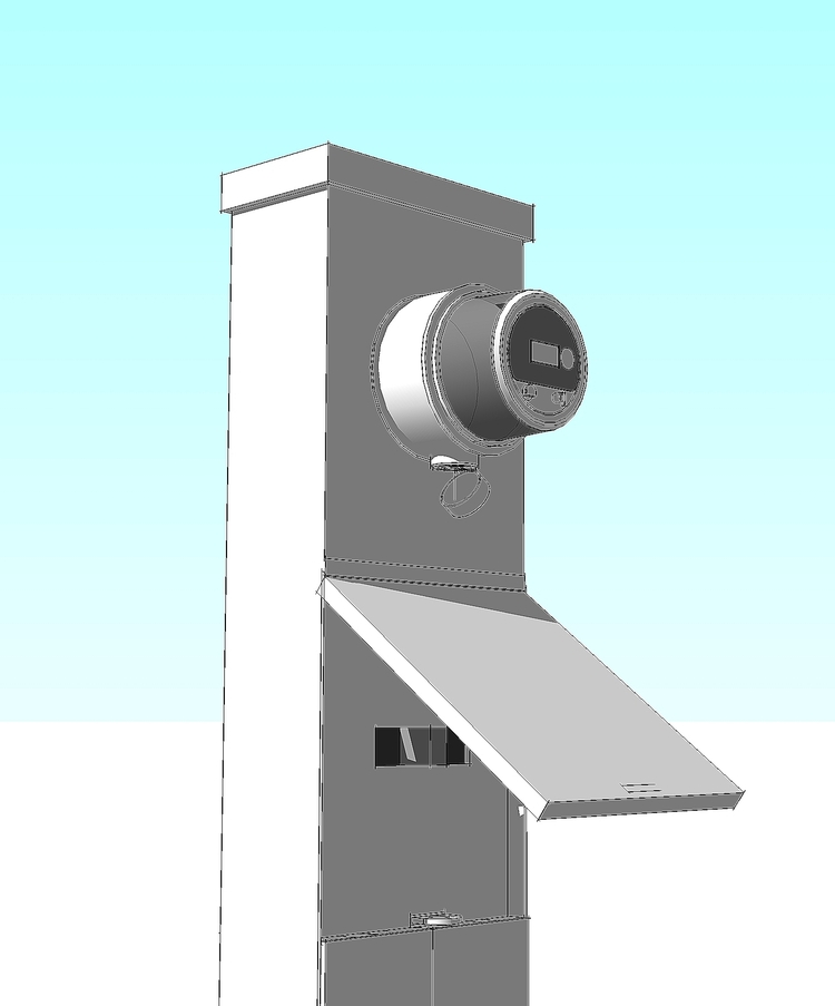
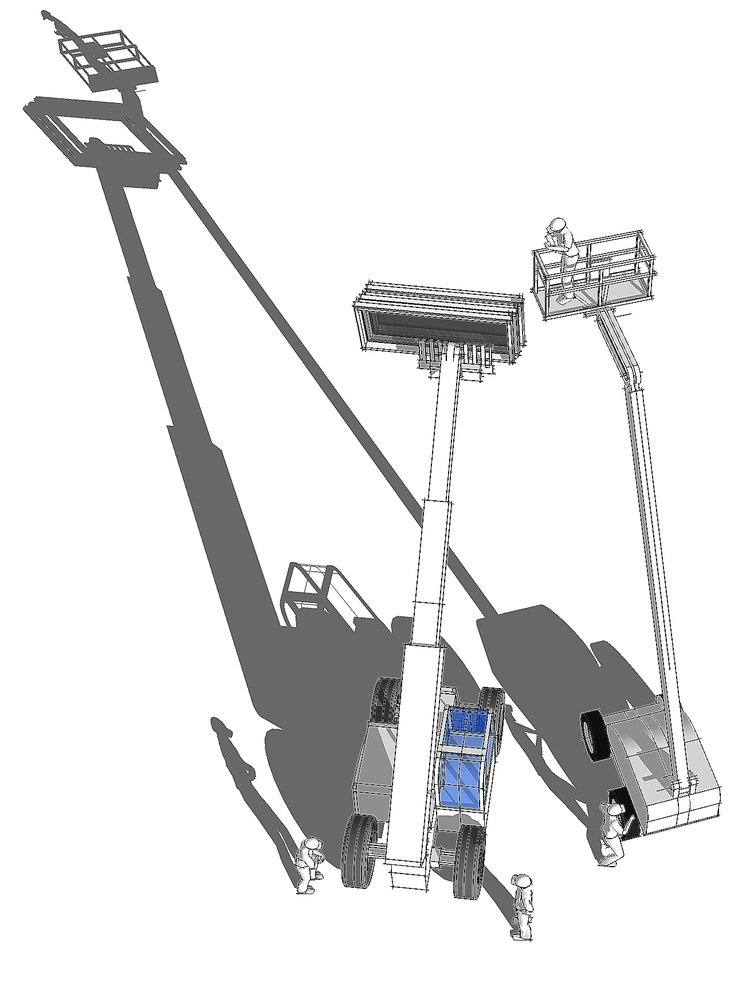
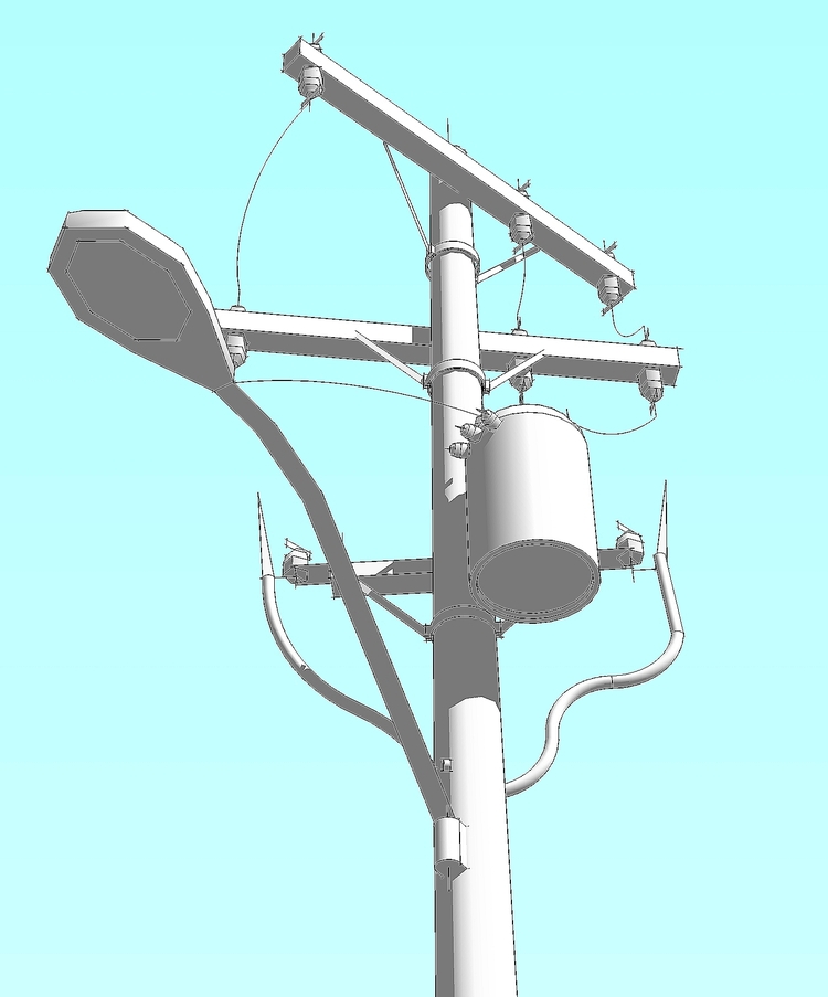
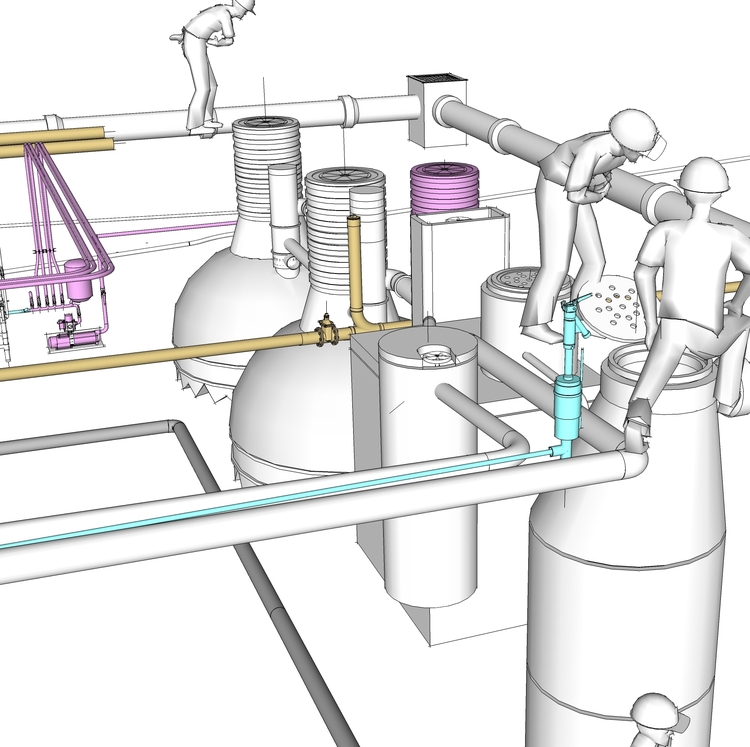
For example, these are low resolution images of a research tool we use to explore alternative concepts for both construction and construction documentation. The images were Exported from SketchUp and are fast to upload or email and simple to paste into a text editor, or slide show.
A video animation of the model can also be uploaded to You-Tube. This particular video is a simplified version of a more comprehensive construction model found in our book, Living SMALL.
You-Tube animations can be embedded in an email, web page, or viewed by anyone who visits their site. Alternately, controls can be set to limit viewers to a restricted group of project players.
The SketchUp construction model
The actual SketchUp file can also be uploaded to Google’s 3D Warehouse where anyone can download it, examine its details closely, or embed it in another construction model. Downloads are done within SketchUp, but the file can also be picked up directly from the website containing the shared model.
Manufacturers and suppliers working to serve the needs of the design and construction industry use this feature to make models available of their own products. You can download this model using this Tiny URL link to the Google Warehouse:
Note that because the model is also “geographically located” it is possible to view the model on Google Earth as a 3D Building. All one needs is the address of the project to search and fly to its location. As readers of our books know, Google Earth is a powerful program able to contextualize a jobsite and help in site utilization planning.
Hypergraphic Communications
In the end, what we’re seeing is a number of emerging communications technologies, including 3D modeling programs, high level presentation media, and growing social networking sites like this blog, Facebook, and MySpace that can be used to distribute construction information.
Each evolution of these technologies brings new power and potential to increasingly aggressive and innovative companies. Giving those that understand how to use these new tools the ability to present their ideas clearly and communicate in ways that were once considered not only impossible, but unnecessary in the markets of just a couple years ago…. . .
Successful companies use 3D construction models to clearly communicate their ideas and win new projects.These models are a powerful way to deliver and understand construction information because they clearly convey the details of a structure and the actions necessary for its assembly.The models also visually communicate questions and alternatives during construction, setting the stage for an efficient and coordinated production process.
Deteriorating Construction Information.
It’s no secret that the quality of construction drawings has been steadily declining.Facing lower fees, higher risks, and the demand for more information, many designers use stock sheet templates, standard details, and server side resources that allow computer operators to piece together hundreds of sheets of documents with little time to check the results.
As a consequence, poorly drawn construction documents set the stage for adversarial relationships that begin with bid clarifications, memos, and addenda and evolve into hundreds of requests for information (RFI) during construction.These RFIs are regularly followed by field bulletins to correct or stop ongoing work and change orders to adjust the scope and cost of the original contract.Add to all this paperwork revised specifications, daily reports, letters, meeting minutes, and emails and the shear quantity of information quickly becomes overwhelming.
Light & Fast Graphic Communications
The value of our books is that they demonstrate the use of SketchUp as a graphical tool that can streamline the challenges of construction communications.Our objective is to show how construction models can be used as a common collaborative point of view.This reduces redundant communications and the time it takes to describe and explain what can more easily by conveyed in an illustration.
Important is that anyone can build a simple 3D model.This means every person on the project team is able to contribute to the project using models to establish a common point of view.
Guerilla graphics
Model construction is quick, simple, and intuitive.Layer and object level controls are used to stage the model for screenshots.These screenshots are edited and imported into a desktop publishing program, or inserted into email, spreadsheet, word processor, or presentation programs.The resulting images represent strategies, illustrate questions and answers, demonstrate solutions, or visually communicate a series of distinct activities.
Completed models are also a resource for new models.Our readers are encouraged to “pick and pull” pieces or assemblies from our models and use them on their own projects.In other words, the equipment, frames, and mechanical systems included in the models with our books can be used to build almost any other project.
For example, the materials and methods found in “How a House is Built” or “3D Construction Modeling” can be reassembled to build a construction model of almost any imaginable house.
In the same way, the equipment, formwork, and mechanical systems found in “Building SIMPLE” and “Being SUSTAINABLE” can be quickly reassembled to represent almost any type of commercial building.
Competitive Construction Communications
If a picture is worth a thousand words, and a model can generate a thousand pictures, a single construction model can easily illustrate even the most complicated assembly.This makes a three-dimensional model a critical resource in competitive construction communications.
Barbara and Dennis Fukai are the people “behind” Insitebuilders, a small press specializing in books for the design and construction industry. All of their construction books are written as graphic narratives using a combination of three-dimensional illustrations, interactive 3D construction models, short videos, captioned text, and interactive media. Their goal is to keep their construction books simple. The objective is to make complex construction information quick to read and easy to understand. To accomplish this they use very accurate 3D construction models built with Google SketchUp. The Daily CatchUp asked Dennis about his reasons for using SketchUp for this purpose.
TDC: What do you see as the real value of SketchUp?
Dennis: I think Brad Schell, the founder of SketchUp, said it best on the cover of our book “Building SIMPLE: Building an Information Model.” To paraphrase, he saw 3D modeling as the best way for everyone to share the ideas, designs, and dreams we all have floating around in our heads. For Brad, everyone, the “professional architect, builder, mom and pop remodeling a kitchen, or a kid designing the next space station…” has an idea that needs to be expressed. In short, his dream was to bring 3D to the masses, and that’s exactly what he did.
What has always amazed me about SketchUp is its intuitive feel. It seems like the tools are right where they should be, they operate almost exactly how one would expect them to, and the program anticipates the little things necessary to make 3D modeling easy for everyone. In fact, the pure genius of SketchUp, is that some how the original @Last team was able to get all of these ideas coded into a simple program that seems to just expand and grow from within its own user base.
And what is truly amazing is that in all our books, with thousands of pieces in hundreds of assemblies, we have yet to find the limit of what even the early versions of SketchUp can do. There is no way any of this is an accident, and I continue to admire how inventive and instinctive that early vision remains in probably the most useful product out there for construction modeling.
TDC: Why use SketchUp for construction modeling?
Dennis: Though it’s a great design tool, SketchUp is more than a pretty face. It also has an important role to play as an information and communications tool for manufacturing, construction, and property development. In fact, its real value is not that it can simply illustrate objects in 3D, but that it can also very quickly model and communicate “time” as an erection sequence, simulated field assembly, or a preconstruction process. (See Dennis’s blog)
We use our books to show how SketchUp can be an effective tool to visually communicate the means and methods of an assembly as a series of distinct events or activities. This is especially important in risk management, but it is equally important in discussing change orders and clarifications because it sets up a visual understanding of a problem from a common point of view.
The result is an increasingly collaborative approach to construction, where owners, designers, and constructors are all able to animate concerns in 3D, illustrate project production over time, test alternative approaches to an assembly, and evaluate schedules and costs as a logical sequence of activities in order to find the best values for a project.
TDC: How is construction modeling different in SketchUp?
Dennis: The speed and intuitive feel of SketchUp makes it easy for almost anyone to build a construction model. The trick is using the Outliner in combination with strict control over the organization of the pieces of the total construction. Layer controls, Groups and Components help, but the basic idea is to maintain distinct clusters of objects as a controlled collection of nested construction assemblies.
Fortunately, almost all estimates and schedules in construction are organized in a work breakdown structure (WBS). This means the WBS quickly provides an over all framework for the pieces of the construction model, including three standard levels of subassemblies, sequences, and the supporting labor and equipment used to actually build almost any complex construction project.
The organizational methods we use for the construction models in our books have evolved with the changes to SketchUp over the years. This means that our readers not only interact with the animated details of complex construction in 3D, but they can also follow through with those assemblies using the hands-on project based tutorials included with every book.
TDC: Thank you, Dennis, for these “insights” and finally here are some exciting (though low resolution) samples from the books:
Construction drawings were once works of art. Not for their detailed precision or extensive notes and documentation, but simply for their expressive representation of a building.In those days, ideas evolved from sketchy schematics to roughly scaled preliminaries, with time to review alternatives and think through their constructability.
Final drawings were inked with ruling pens on pressed linen using T-squares, triangles and curves to shape beautiful illustrations of the building.The result was a set of drawings based on a thoughtful process that was fundamental to the pride and challenge of a team of good draftspersons.
This was also an era when builders and drafters could take the time to collaborate and work together to shape a building during its construction.The finished drawings were no more than a starting point for a working relationship between skilled tradesmen and women who could take pride in abilities that they had acquired through years of apprenticeship and training.
With the advent of time saving instruments like parallel bars and drafting machines, ideas continued to be drawn, but the speed and versatility of these new instruments meant details could be discussed and noted on the drawings entirely within the designer’s office.In other words, rather than rely on open relationships on the jobsite, drafters began detailing the “requirements” for the constructions before the drawings reached the field.
Controlled collaboration
This ability to presuppose the input and experience of the builder meant construction drawings soon lost their place as the start of a conversation.Working drawings became contract documents, with detailed notes and specifications penciled onto sheets of vellum outside any input from a builder -- collaborative opportunities for mutual cooperation were quickly forgotten.
Then computer aided design (CAD) became an essential drafting tool silencing even the skilled draftsperson.With the advent of CAD, once open drawing-board-conversations between skilled designers were inadvertently lost to the memory of a machine.Newly trained CAD operators labored in “virtual” isolation to manipulate lines and letters, using templates and libraries of graphic data with conversations limited to redlined corrections and data input.What little construction knowledge that could be exchanged was dulled by the monitors of isolated work stations.
The latest technical development takes this breakdown in any collaborative approach one step further.With building information modeling (BIM), software publishers promise that a set of two-dimensional documents can be “parametrically” generated from detailed design models.With the expanding power of graphical computers, hundreds of sheets of drawings and thousands of pages of specifications can now be automatically extracted from three-dimensional databases, leaving little time for any discussion.
Silenced by the technology
Ironically, both the builder and the practiced draftsperson are now silenced by a widening technical gap.Worse yet, the computer operators who build these parametric models are even further removed by the same technology.As the puppets of project management, they have been reduced to performing tasks with limited understanding of the nuances of the real-world constructability or the implications of the plans automatically generated by their computers.
In response, large construction companies have installed their own graphical work stations.Operators struggle to generate preconstruction and as-built models using the same design software to anticipate and resolve conflicts and problems that may occur in the field.The use of this software by constructors indicates a commitment to cutting edge information technology, even though the real value of these programs is its advertised potential to automatically convert 3D models to 2D contract drawings (parametrically).Not something many builders need or want in the real world.
The challenge of course is to respond to the potential of this new technology, without lo
sing the exchange of ideas and interaction fundamental to discovering solutions in the construction process.Like the once skilled draftsperson, professional builders can easily be buried by a protracted learning curve, cut off by a technology that blurs the essence of what it means to be a builder.
Construction models are not BIM
A construction model graphically defines scope and anticipates real-world conflicts and alternatives with little need for two-dimensional drawings.These models mix sequence animations and assembly and process simulations to communicate ideas spontaneously in an ongoing construction process.
Important is that a construction model differs from a designer’s BIM model.While in theory a detailed BIM model incorporates the subassemblies necessary to produce a set of contract documents, a construction model intends to graphically represent ideas in support of a continuing conversation in real-time construction.
In practice, the construction modeling process helps builders think through and visualize more than the finished assembly.It is fundamentally a tool to hypergraphically plan and anticipate the impact of change and the values of different approaches to the same result.In other words, construction models embody the means and methods that interact and evolve with the variable of real-world construction.
The strength of a construction model must therefore be in the simplicity of its production.Any technical distraction, other than to directly represent a construction concept and clearly illustrate a series of actions, only distracts from its communicative potential for the seasoned builder.
Keep it simple
A three-dimensional construction model must therefore be absolutely dead simple to build.The software must reduce the production of the construction model to the essence of its value to hands-on builders.This means learning the program must be intuitive, requiring no more than an hour or so to gain proficiency, yet capable of generating the kind of detail that can be used in a variety of interactions.
To meet these requirements there are several 3D programs, any one of which could serve the needs of different builders and all of which are free.These programs range from basic modelers with simple sets of construction tools like DeleD and 3Dbase to photorealistic modelers like POV Ray, Blender3D, and TrueSpace from MicroSoft. Of course, the most popular 3D modeling program and perhaps the most intuitive for hands-on construction modeling is Google SketchUp.
In the end, the choice of the modeling program is really unimportant.The most important requirement of a construction model is the model builder’s underlying and fundamental understanding of the construction process.From this basis, a construction model can communicate an approach, plan a process, and think through alternatives.
Like the early pen and ink drawings of our graphic tradition, the resulting three-dimensional images will then focus the conversation on the actual construction, helping all the project players, on and off the jobsite, to literally see and share the same point of view.
Al Hart of Render Plus Systems announced the release RpTreeMaker, a free integrated plug-in for Google SketchUp that creates realistic trees.
RpTreeMaker is a new, free, product that construction modelers can use to create realistic, fractal trees and place them into the SketchUp model as 2D face-camera components. Program parameters (Tree Type, Number of Trunks, Bending, Crookedness, and Leaf Type) let users easily create custom trees for a construction model that might be critical to planning the production of a project.
This new plug-in makes it possible to add depth and realism to a SketchUp model, including quickly and easily adding a large variety of trees to match existing site conditions.This would be important in site utilization planning, selectively clearing existing trees for construction, or modeling a specific management technique for working on heavily wooded jobsites.
Render Plus Systems is a software development group in Centennial, Colorado devoted to adding functionality to Google SketchUp. The company fills many of the gaps in SketchUp with design tools that the Google development teams have overlooked.
Render Plus started out with two products: 1) RPS 3D PDF, which lets SketchUp users create interactive 3D PDF documents from SketchUp drawings that could be especially useful in construction communication, and 2) a set of programmatic routines called RpTools that makes it easier to place and manipulate model components in order to fill rooms and quickly populate a working jobsite with repetitive element such as safety railings, fencing, scaffolding, or falsework.
Their most popular product is IRender nXt, an integrated photorealistic renderer for SketchUp, that uses lights, reflective materials, plants and 3D Objects, to create high quality renderings from a SketchUp model.
The SketchUp Outliner organizes a construction model so it can be used to display the sequence and time embedded in the model’s assembly. In fact, without the ability to visually represent time, SketchUp would have little value as a real-world construction communications tool.
Though its features are often overlooked, the Outliner makes it easier to:
1. Break the model down into the pieces of its construction. These pieces are the “named” Groups that make up the deconstructible assembly of the construction model. Every piece is then joined as part of a subassembly or Group of Groups.
2. Stage these subassemblies according to Hide and Layer commands in the SketchUp program. These subassemblies include the operational parts of equipment and materials, the components of subcontracts, and the visual representation of scope within the construction phases or processes.
3. Scenes are created to construct and deconstruct the subassemblies, in order to animate the sequence of a task and navigate through the construction site. The Outliner is central to the control and display of the pieces in these Scenes.
With the Outliner dialog box open, try these basic steps:
1. Fabricate the individual pieces on Layer 0, then Group and name the piece. Note the named Group is now visible in the Outliner. To a constructor, it’s these individual pieces that are important to the construction. Fabricating and naming the pieces separately means they can be identified and controlled within an assembly.
2. Group the piece-groups and name them as subassemblies. Note that the named subassemblies are now visible in the Outliner as nested Groups. The subassemblies organize the model in phases or sections in the same way they are organized in the real world.
TIP: You can cut, copy and paste the names of the pieces in the Outliner. You can also drag and drop the pieces from named Group to named Group.
3. Use Scenes with the Hide and Layers commands to control the pieces and the subassemblies. To Hide a subassembly, Right-click its name in the Outliner. You can also place individual pieces or entire subassemblies to a named Layer and then turn layer visibility on and off in the Layers dialog box.
4. When ready, create a Scene to capture the current view. Each Scene can be exported as a 2D image and inserted into a text document, spreadsheet, or slideshow. A series of scenes can also be played as an animation.
TIP: You'll see these techniques first explored in our book 3D Construction Modeling. They then evolve through all our books into the 13 tutorials in our most recent publication, How a House is built: With 3D Construction Models.
We’ve just published a follow-up to the book 3D Construction Modeling.The new book, How a House is Built: with 3D Construction Models is a how-to book on construction modeling using the latest version of SketchUp.The modeling lessons in the book are wrapped in the virtual construction of a small, simple, and sustainable house that covers the step-by-step and day-to-day details of residential construction from surveyed layout to MEP finish.
.
The book uses the same detailed 3D models, captioned text, short videos, and 3D illustrations we use in all our books, but its final chapter differs from our earlier publications because it begins to explore how a contractor (or designer) might use the web as a visual interface to communicate construction information.
.
Though all our books come with CDs that act as a window to the Internet, offering links to the models, video downloads, and the web resources used in the book, this is the first time we’ve mounted a chapter on the web in an attempt to explore a fully interactive construction information environment.
.
A paper-based model for a paperless jobsite
Not to say that the resulting web pages are so great, or that the over all research potential has really even begun to be explored.But what occurred to me as this section of the book was being developed is that the original notion of paperless project documentation on a rapidly moving construction jobsite is, in practice, constrained by a fundamental assumption that paperless information should follow a paper-based model.
.
In other words, in order to find a paperless environment, early attempts by constructors have been to use paper as a template for electronic translation.Documents are simply posted online as PDFs, text or spreadsheet files, or a collection of JPEGs. Worse yet are the orphaned CAD.dwgs -- complete with bundled X-refs and a conglomeration of programmatic references which, of course, only actually work on the computers that originated the graphic files.
.
Even more challenging is that these electronic files are often emailed or quickly posted and indexed as a list of cryptic titles with no visual references or clue as to what they are or how they might fit together.Over the life of even the smallest project, electronic information becomes as worthless to day-to-day management as the growing pile of printed boilerplate specs crowding the back of a construction trailer.
.
The resulting indices are handy archives to store and retrieve evidentiary information, but a long way from the visual and dynamic potential of what the web might bring to support real world, real time, construction management.
.
A construction information environment
What is interesting to me in this new book is the combination of the three-dimensional storyboards used in all our books, mixed with manufacturing links, interactive details, animations, and streaming videos – both from the models that illustrate the book and publicly posted videos on U-Tube and similar websites.
.
It’s as if the chapter’s six web pages flesh out the construction information I’m trying to convey and expand on the three-dimensional models, not as 4D or nD, but as an information environment that points in a direction that casts a dark shadow over the existing paper-based paradigm.In fact, the resulting chapter could not be printed.A single page of multidimensional information cannot be tied to paper or printer and must remain in its interactive, electronic state.
.
Readers, or perhaps users, must then be induced (or enticed) into a participatory world.Moving from topic to topic and link to link, taking in the information in response to actions that only they can initiate.The information is therefore layered in relational stacks of visual data, stepping beyond the role of a static construction document and back into the fold of real time, relevant construction communication.
.
Understanding motion and movement in this graphical information environment is something we’ll continue to test and explore in our next books.But the notion of moving through the data, inferring references from graphical clues, and presenting information in deepening layers of relevance, has the potential to parallel and somehow represent the same controlled chaos we find on almost every jobsite.