Wednesday, April 18, 2012

Beyond Fashion and Style

Another working except from our new book: Surviving @ Net Zero: Building Shelter for an Uncertain World (Nov 2012)

Most would agree that the cultural context of a building influences the characteristics of its physical form. These are usually seen as decorative features, part of a temporal and evolving style, with no universal truth or purpose other than to entertain the aspirations of their clients. When they work, the resulting buildings fulfill the expectations of their time and place with no lasting influence on society or construction technology.
Insitebuilders: Surviving @ Net Zero: Shelter for an Uncertain World
Even classic building styles are self-defined by the historic, religious, or political discourse that surrounds them, icons of certain cultural values and not the result of some deeper social significance or aesthetic. As a result, we live with buildings that reproduce contemporary ideals only to be oddly antiquated with the passing of time.   

The Vernacular of Net Zero
By contrast, a vernacular architecture describes the physical characteristic of a building that reflects a common method of construction that uses local labor and materials to satisfy the shared needs of a community without adding superfluous stylistic decorations. There is no feature in a vernacular that goes beyond the functional requirements of its existence as a building. As such a vernacular is not influenced by changing trends or fashionable statements that find themselves dated and worn in time.
Insitebuilders: Surviving @ Net Zero: Shelter for an Uncertain World
Vernacular buildings are purposeful, reflecting a human response to their environmental, economic, and social context as a collection of inherent qualities that are often dismissed as crude and unsophisticated by proponents of more self-conscious building styles.
Insitebuilders: Surviving @ Net Zero: Shelter for an Uncertain World
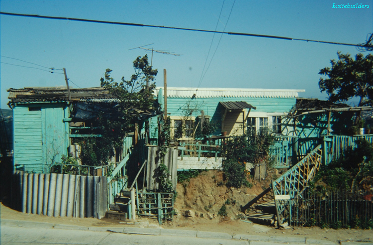
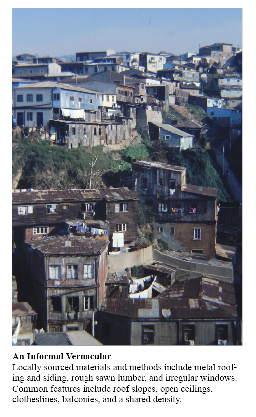
The buildings seen in the informal sector reflect many of the values of a vernacular architecture. While some include personal expressions, they all use the same locally salvaged resources, built with simple hand tools and an intuitive, almost primitive approach to their construction. The result is an immediately recognizable sense of disorder that reflects the essence of their function as pure shelter. Insitebuilders: Surviving @ Net Zero: Shelter for an Uncertain World
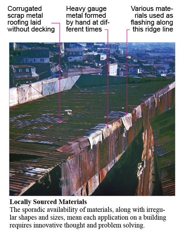
This absence of order is of course shaped by impoverished technical limitations, economic exclusion, and a subsequent social marginality that has reduced these buildings to their primal purpose. As such they are a natural response to a basic need for self-preservation as a derivative of a net zero economy with no governing social mandate or regulatory authority to care for them.

Intuitive Construction Methods
What’s interesting is that these informal buildings are slowly reinforced by the security that comes with tenure on land occupied with varying levels of economic success. As such, they are not simply the result of a community of people desperately and haphazardly assembling buildings.

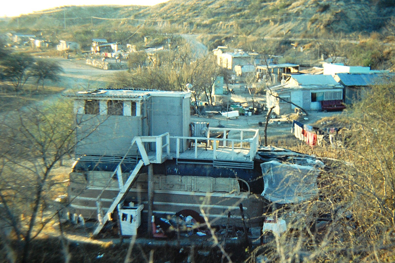
Instead there is a method to their construction that includes a carefully considered assumption of the potential of materials and methods, with clear evidence of varying levels of construction quality. The distinct features of an informal vernacular are driven by the limitations of the materials, tools, and skills available to their builders.
Insitebuilders: Surviving @ Net Zero: Shelter for an Uncertain World
Though it’s easy to discount the resulting structures as completely inadequate, look closer and you see details that require solutions that would be difficult to duplicate with formal construction methods.

Insitebuilders: Surviving @ Net Zero: Shelter for an Uncertain World
 As a result, what we see in these informal buildings is an architecture stripped of the systemic support of an industry of processed materials and practices, leaving the informal builder to invent and implement solutions that are fundamental to their personal needs. Design exists as physical form of three-dimensional problem solving, depending solely on available resources and reduced to the essence of self-determination, imagination, and inventive thought.

The 3D modeling methods of these unique builders follow a survival strategy that holds clear lessons for construction in an uncertain world.
.

Tuesday, March 20, 2012

Beyond Construction Modeling

It doesn’t take more than a few years teaching in a construction school to realize construction students are definitely a breed apart. This fact is particularly interesting when the school is within shouting distance of an architectural school.


For some reason, designers and constructors just don’t mix well. This, of course, is nothing new to anyone working on a jobsite, but it’s particularly interesting that this innate difference in personalities begins well before anyone enters a design or construction program.  

Bimification of Craft
Of course professionals work together effectively no matter what their personalities or motivations, recognizing a mutual interest in coordinating their efforts to get a project built. But the rationalization of the entire construction process tends to diminish both the craft of producing a design and the craft of building a building. In practice, the industrialization of the products created by designers and builders has been going on for a very long time and though both recognize the importance of the others’ work, few practicing today remember the draftsmen or carpenters that were once masters of their craft.

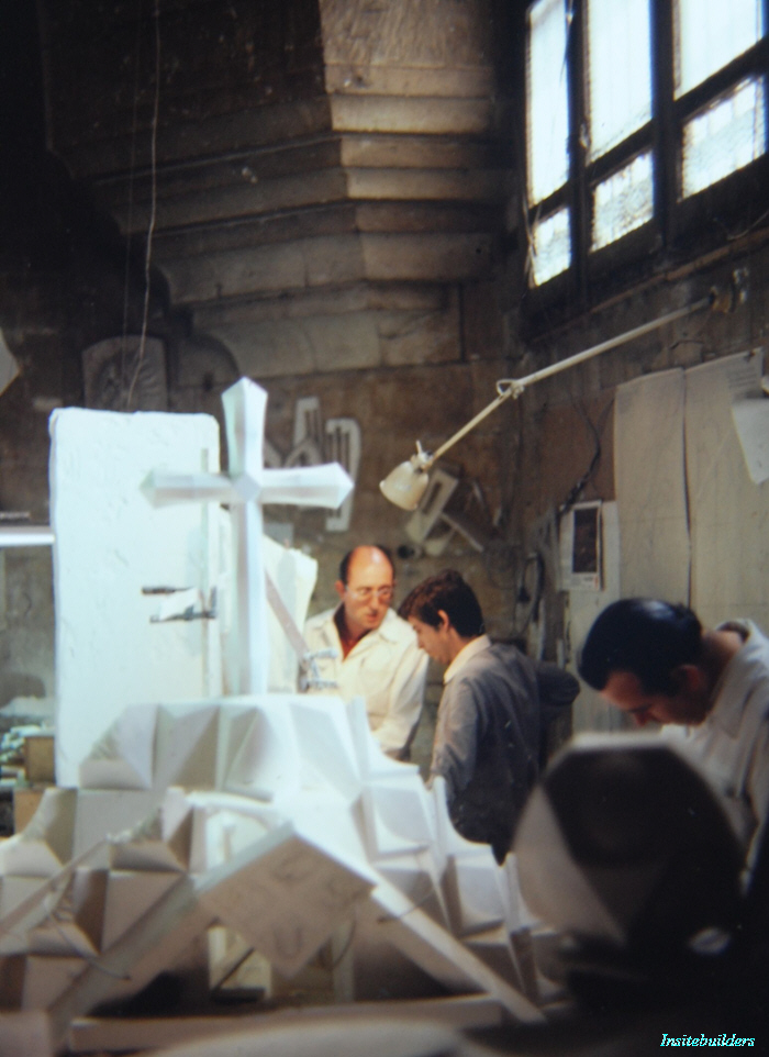
Sagrada MasterBuilders - Insitebuilders
In a fast paced bimified world, it’s very rare to meet either a designer or a builder who has achieved the level of expertise once seen with the legendary masterbuilders. Perhaps things are just too complicated now for individual expression. Where a sheet in a set of construction drawings was once drawn by one person and checked by another, CAD drawings are now a mix of overlays, cross references, imports, and paste-in-place, all following a preprogrammed, almost robotic computerized system.

Like manufacturing a new car, buildings are designed and assembled through repetitive work, maximum efficiency, and carefully managed production. When it works, it gets the job done, but the results are far from a personal expression of any individual’s skill.  

Techne of Craft
Sociologists see this loss of craft as the outcome of specialization, a function of modernity and the reduction of the master craftsmen to wage workers without the time or interest in perfecting their work. Ancient Greeks described the separation of craft from work as a philosophical trait they called “techne.” Techne is the mechanical skill, the living knowledge of a craft, as an understanding of something that brings a sense of satisfaction from a familiar expertise in making or doing.


Techne was once seen in singular objects that were drawn or created with a focus on the physical act of doing, not as an art, but as the result of the actions necessary to proudly put something together with one’s hands to solve a problem or make something that wasn’t there before. The objects that result come from a deep understanding of the tools and materials that are the manifestations of their craft.


The industrialization of craft is of course necessary for human progress. Most would agree there’s no way we could do what we do now in a purely craft-based economy. Considering the systems and specialization, let alone the growing intelligence of both the building and design documentation, we can only dream of those good old days. I’m happy I was a part of them.

Techne @ Net Zero
At the same time, techne exists in design and construction in what appears to be the absence of craft. This is the folk art of pottery and paint, the fantasies of individual expressions.

 
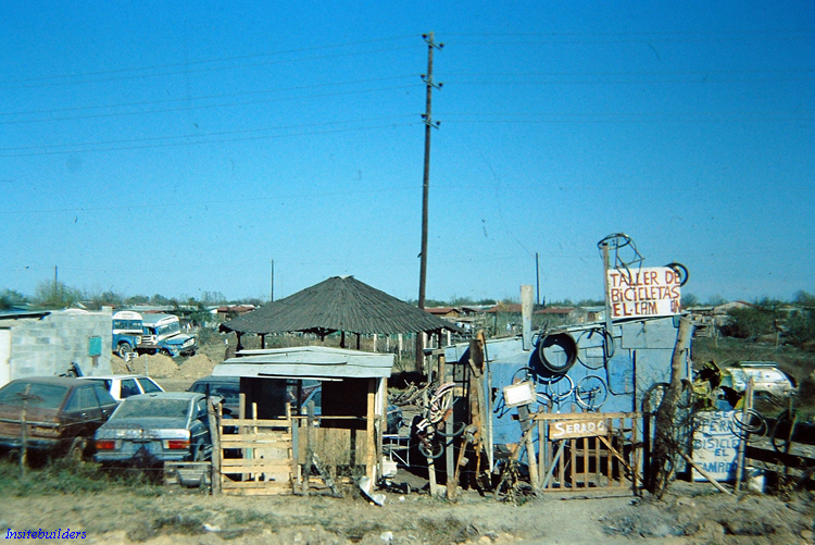
For construction professionals, techne is most apparent when we look at the disordered architecture of the informal sector. These are buildings where craft appears to be excluded from both the details and structure of their form. At the same time, if you look carefully (with the eye of a hands-on do-it-yourselfer) you see the ingenuity and determination embedded in an architecture with no presumptive form, no practiced pretense.

Informal bike shop - Insitebuilders
At first glance, these buildings may seem to be the antithesis of techne. Seen from a developed and disciplined world, they look like unconsciously erratic interpretations of architecture, expression of both untutored self-determination and limited imagination. But look again and you might see a reflection of the personalities we once held before being trained as designers and builders in a post modern world.

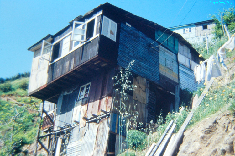
 Informal Builders - Insitebuilders - Casa 8 Elevation
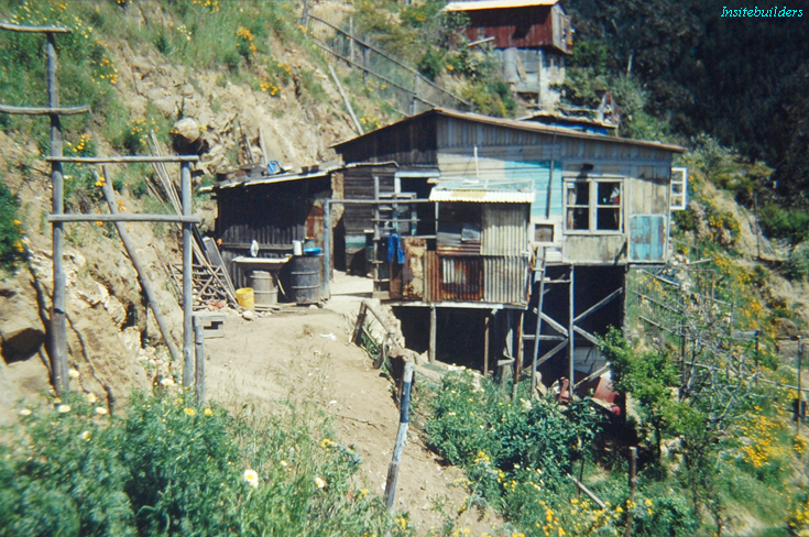
Important is that these buildings stand as the result of impoverished humans responding to the need for shelter with little or no planning, using random and dysfunctional materials, limited tools, and a disordered process that reflects almost none of the formalized systems of an “educated” industrialized society. With no power, scaffolding, or equipment, this is architecture put together by hand with none of the practiced rigor of a preconceived plan or the processed consumables necessary to analytically assemble an orderly product.

Informal builders - Insitebuilders - Casa 8
Standing outside the formal constraints of a rational process, they are a unique human form, distillations of the essence of intuition and invention where shape and substance are created purely out of necessity and an instinct for survival.

Informal roadside sculpture - Insitebuilders
As a purely organic structure, they are built like sculptures with randomly collected materials pieced together to create an object that mixes both doing and design on the margins of rational industrialized thought.  

Beyond Construction Modeling
Study these buildings again as a construction modeler and you see an object that cannot be built as a 3D construction model, first because the pieces and placements don't conform to the simplified geometry of our bimified three-dimensional axes. Second, though the elevations might be photographically textured as a rendered model, the assembled materials cannot be organized in a computer to predict or inform a construction process.

Informal builders - Insitebuilders
Finally, neither the design nor construction can be reduced to an hourly wage. There is no schedule to manage, no deadlines, just an ongoing commitment to self-reliance and determination. Beyond craft or techne, what we see as a result are the purposeful limits of construction modeling.

When the innate personalities of designers and builders are left to wander without the professorial inputs of an institutionalized post industrial world, one is only left to marvel at the techne seen in these informal constructions.
.

Wednesday, February 15, 2012

Simple Process Model

SketchUp models are easily used to animate construction phases. They are quick to set up and can be important in illustrating a schedule or particular sequence of construction that might be critical to a bid or negotiation. Here’s an example (with no sound):


The animation was set up in five steps:

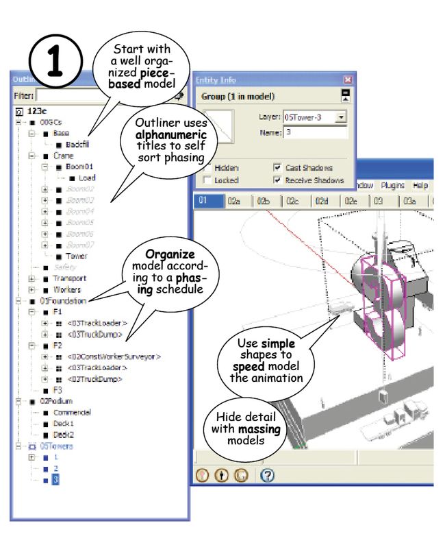
1. Organize the pieces in the Outliner. Start with a well organized construction model (use the 1, 2, and 3 method in the previous articles). Pieces should be grouped and nested according to phase and subcontracts and named alphanumerically so they self-sort in the Outliner. To preserve the original model, use Save As to save a version of the file for the animation.

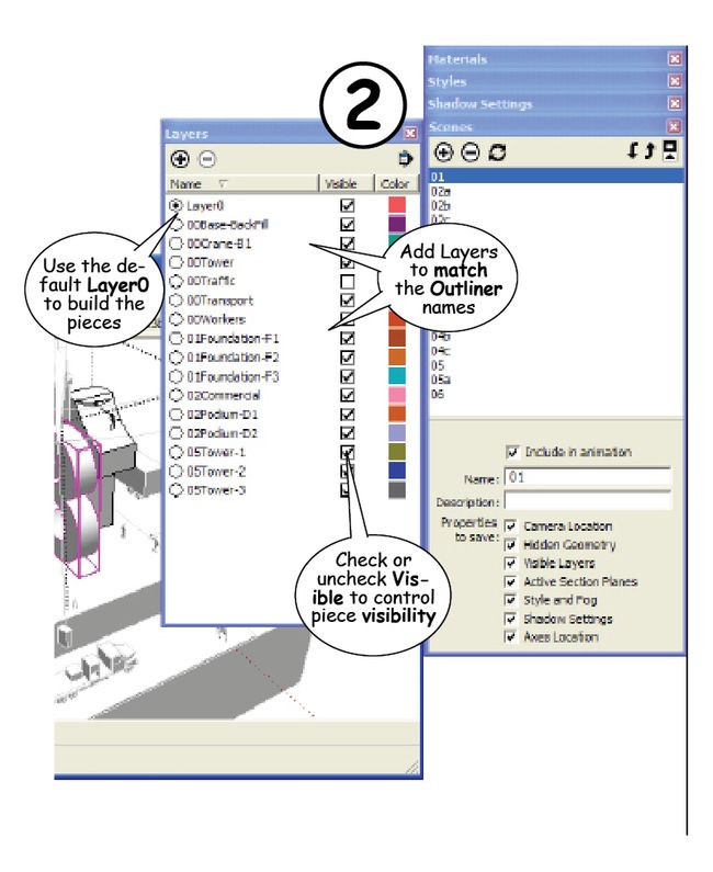
2. Add Layers for control objects. Add Layers to match the alphanumeric names of the pieces, Groups, or Components whose visibility you want to control.
 
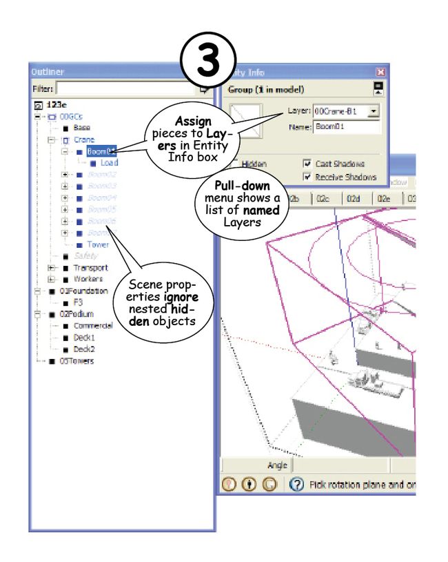
3. Assign pieces to Layers. Select the control object in the Outliner, then use the pull down menu in the Entity Info box to assign it to a corresponding Layer.

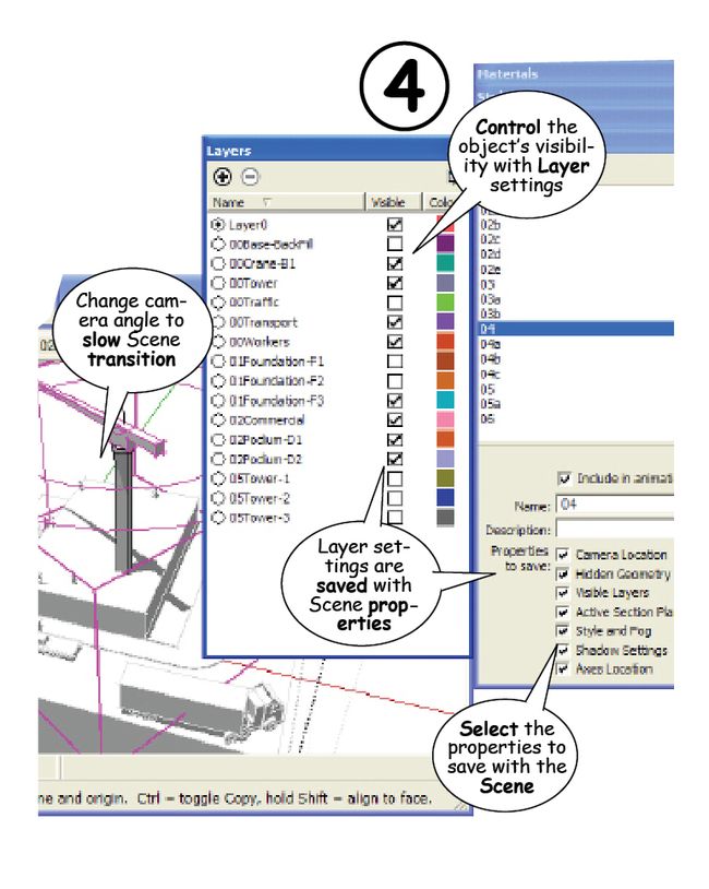
4. Set up Layer visibility and Camera. Check or uncheck “Visibility” in the Layers dialog box for each Scene. Change the camera angle, even if only slightly to slow the animation down. Remember you can set the seconds of the transition time between Scenes with the Windows > Model Info > Animation settings -- use at least 5 seconds with no delay time between Scenes.

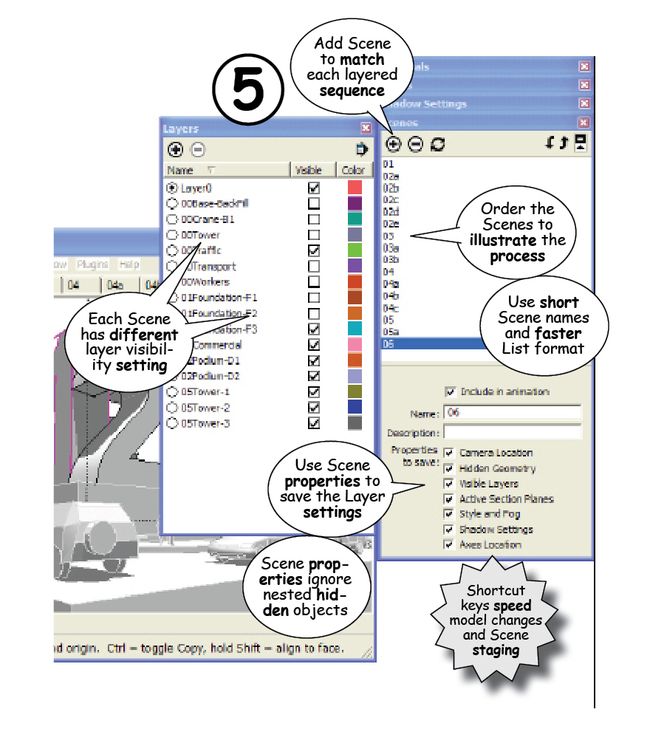
5. Add the Scene. When the Layers and camera angle are set, click to add the Scene to the sequence. You can add more Scenes and reorder them in the animation with the Up and Down arrows at the top of the Scenes dialog box. Test the animation by clicking through the Scene tabs or the names in the Scenes dialog box before playing the final animation for export or recording. 05: Test SketchUp Scenes  
SOME TIPS:
a. Use simple shapes with minimal detail. Increase detailed Scenes later. 
b. LayerO is the default. Only assign Layers to control visibility. 
c. Shortcut keys are critical to fast and simple model construction. 
d. Hidden pieces within a group are not recognized by the Scene property settings. .

Thursday, January 12, 2012

Simple as 1, 2, 3

SketchUp is not a BIM modeling program. It does not format components or tabulate descriptions, there is no related data assignment, it doesn’t really work well across multi-platforms, it will not generate analytical reports and it will not automatically or even semi-automatically export a 2D drawing. And it is definitely not a drafting program -- though it will produce a great set of construction documents -- if you know what you’re doing.

It’s not about BIM At the same time, anyone can use SketchUp to build a detailed 3D model. Users include high end designers who render buildings in some pretty amazing ways, plus thousands who use SketchUp to visualize space, color, form, and shadow, lay out a stage, storyboard a movie, graphically illustrate a narrative, build a game, or teach almost any subject from K through 12 (and 13-25).

Insitebuilders-Fig1, Blog120112 SketchUp Scenes 

At the same time, no real constructor needs a model to visualize a set of 2D construction drawings -- it’s not that hard. Students even learn to imagine space and draft 2D floor plans, elevations, and sections in junior high school – though they prefer building 3D models.

Construction modeling is process modeling Important is that the real potential of construction modeling is in simulating a process. A construction model animates time. Here are some recent examples:
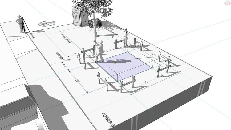
  • Site utilization planning (SUP), mobilization, and startup
  • Tricky lifts or placement of concrete, steel, and air handlers
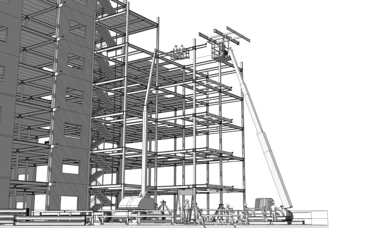
  • Sequence safety lines while decking a high rise steel frame
  • Coordinate labor & material as floor phases, 36 story build
  • Simulate safety changeovers in placing fall protection
  • Designate safety zones and restricted areas changeovers
  • Simulate stair & deck installs on fast track steel frame
  • Determine distances, timing, staging, & material movement
  • Phase and process demonstrations and method sequencing
  • Scale safety zone markers for overhead material movement
  • Coordinate move-on, staging, & subcontract start-up
  • Scale a lay-down to maximize temporary dry storage
  • Crane arcs into storage areas and placement to grid lines
  • Most of you get it….it is not about BIM, drawings, or design
Insitebuilders.com-Fig3, Blog120113 - Process simulation
 
Simulate process as easy as 1, 2, 3
  • Step 1: Think out of the box, everything comes from a box.
  • Step 2: Inferences & guides to assemble a piece based model
  • Step 3: The Outliner and components control time captures
Once built, a static piece-based model can then be deconstructed to illustrate a process as a clickable series of steps or phases, a video that moves from place to place to record different views of an assembly process, or an animation that both anticipates and simulates movement on the jobsite.

Here are three simple examples to try:  

Clickable Scenes


Scene Properties used to set camera location, field of view, time/shadows, hidden objects, layers, and annotations. Click here to download the model.  

Video Capture


Animation settings used to set delay and transition between Scenes. Video then exported as a movie or captured with one of several free video capture programs. Click here to download the model.  

Motion Capture


Use the same scene by scene animation technique film makers use to capture CGI motion. Click here to download the model.
.

Tuesday, December 13, 2011

#3 The Outliner Organizes the Process

The real advantage of SketchUp as a construction modeler is that it can quickly illustrate or animate any sequence of events from a piece-based assembly.  Notes and dimensions are easily added to exports and the results inserted into working documents, presentations, and email during an ongoing construction process. 


Review Steps #1 and #2
#1.  Each piece begins as a box. Start with a rectangle, extrude it, then shape and modify the box to match the specifications for that piece.  When ready, group and name the results.  Make them SketchUp Components when you know there are going to be several identically scaled clones of the same piece. 

#2Assemble the grouped objects using one of the many Inferences and Guidelines built into SketchUp.  Use the Move and Rotate tools to snap the pieces into position and the Control key to make copies as you build the model.  

Once the construction model is assembled, it can be quickly staged for Export as a 2D Graphic or Animation using SketchUp’s File Menu.  Deconstruction for illustrations and animations are controlled by the SketchUp Outliner and Scenes. 

The Outliner
Use the Outliner to nest the named groups into subassemblies that represent subcontracts or sequences that will be important to the processes you may want to illustrate.  


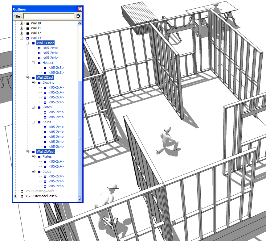
Group the pieces by selecting them in the Outliner with the Shift or Control key.  The Shift key lets you select a series of pieces and the Control key allows you to pick and choose the pieces you want to be in the nested group.  Once selected, use the Make Group command in the Edit Menu and immediately name the new group.  A Shortcut key makes it possible to group objects by pressing a single key.

Once a group is formed in the Outliner, you can drag pieces in and out of that group, double click a name in the Outliner to edit that piece in the 3D model, or combine and reorganize several groups into more complex subassemblies. 

Setting up the Scenes
Use the Orbit and Pan tools to position the camera angle.  Then select any piece or group in the Outliner to Hide or Unhide it and change its visibility for each Scene.  


When ready, use the “ + “ symbol at the top of the Scenes Dialog Box to add a Scene along with the “Properties to save” with that Scene.  Scene names and descriptions help identify content in the Scene, and the “Include in animation” check box will schedule the Scene for export to an animation.  Transition and delay settings are found in SketchUp’s Model Info Dialog Box in the Window Menu.


Annotations and dimensions can be added to each Scene.  You can also capture or Export the Scenes as a 2D Graphic or Animation for further editing in a draw or image editing program, or insert them directly into a working document.

Controlling the visibility or motion of individual pieces in the subassembly is a little trickier, I’ll cover that next time.

Tips
Use a library.  Every piece only needs to be made once when it’s saved to a library.  This means after a couple of models, rapid assembly is possible because you simply drag and drop the pieces into the model from your own collection of construction materials.

Annotate the images.  Use a Draw program to edit and annotate exported graphics.  A free version is included in OpenOffice, or use any of the many free screen capture and image editors found at Only Freewares.  Faststone and PicPick are probably the easiest to use free programs for image captures and quick annotations.

Export animations.  You’ll find the Export Animation feature in the free version of Google SketchUp produces a pretty basic low-resolution animation.  Check out one of the many video capture programs found at Freeware Home when better results are important.  I use the free version of CamStudio for AVI movies and Wink for Flash animations.

Thursday, November 10, 2011

#2 Piece-based Assembly

A 3D construction model starts by first “fabricating” the pieces for the construction and then assembling them exactly as they would be put together in the real world. You can make the pieces as you build the model, or copy and paste them from any previous models. Inferences and guidelines simplify the assembly and the final quality of the construction.   

SketchUp’s Components or Groups?
The key to fast construction modeling is to keep the pieces named and organized so that they are readily available for both field changes and new constructions. The best way to keep a large collection of proprietary pieces organized is in a library folder on your hard-drive.
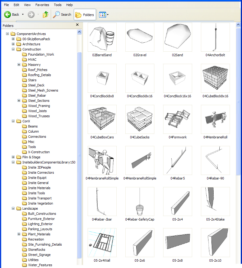
Insitebuilders - SketchUp Component Library
Alternatively, for some projects, you might want to set up a virtual staging area in the same or a separate SketchUp model file. Lay-down yards or staging areas help visually control materials and manage inventory. 

Pieces you drag into a model from a library folder are always Components, while pieces you copy from a virtual staging area can be either Groups or Components. The difference is important because Groups can be edited without affecting copies of the group in the same model. But Components must be made “unique” so they can be edited without affecting their clones or matching copies.

For a construction model, minor changes to a series of Components can quickly overwhelm even a simple piece-based assembly. It’s much faster to Explode, Group, Edit and rename the Component as a new Group, especially if you use the Outliner to track a materials list.
Explode, regroup, and rename  

Built-in Inferences
Inferences, as visual hints in SketchUp make it possible to quickly assemble the pieces. There are three basic types of Inferences that are important to construction modeling:

1. First, there are the Inferences found on the body of the piece itself. These include edges, faces, midpoints, and corners. Each is a snap point for one of SketchUp’s tools.
Typical Inferences

Hover over the piece with the Move or Rotate tool to see inference hints. Then click to snap the tool to that position and start the command sequence.

2. Motion Inferences are red, green, or blue dashed lines that become visible as you Move or Rotate a piece parallel to a SketchUp axis. The Shift key constrains the motion. Press the left, right, or up arrow key to lock movement to an axis. The Control key is used to leave a copy.
 
Typical Assembly

3. Reference Inferences are similar to motion Inferences. They display a dotted line when two Inference points are aligned. Touch the reference Inference point with the cursor while moving or rotating a piece into position to let SketchUp know the desired alignment. Here’s where the Shift or arrow keys are often necessary to constrain the move.  

Centerlines and guidelines
To assemble cylinders (pipes, tubes, and fittings) use mating extensions. The extension can be a projection from the centerline of the piece or any other axis important to the assembly. A fixed length extension makes it possible to quickly join their endpoints and then move the pieces together.
 
Extension lines

Guidelines are necessary to ensure the quality of the final construction in the same way stringlines and chalklines are required in the field by any good builder. They act as temporary references for site layout, as well as intersecting snap points to locate plates, studs, and rafters. Guidelines are also important to center window and door frames, position equipment and furnishings, and install parts of a building’s system.
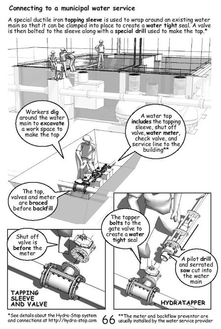
Insitebuilders - Being SUSTAINABLE, page 66  
Piece-based process model
When pieces are assembled and tracked in virtual construction in the same way as they would be on a jobsite, the sequence and scope of the work is automatically built into the construction model. And when these same pieces are nested into sub-assemblies, phases, and sub contracts in the Outliner, their visibility can also be controlled. This makes it possible to both illustrate and animate the scope of the work, adding new potential to your practice and your market presence as a builder and construction manager.

ConXtech: A Revolution in Steel Framing Systems

.

Thursday, October 13, 2011

#1 Think Out of the Box

The key to SkUp as a construction modeler is to think out of the box. Unlike a more complicated BIM or solid modeling program, the free version of Google SketchUp is a simple and easy to use surface modeler. That means it’s very quick to make, modify, and assemble the pieces of a building or other structure. Important though is that it’s this piece-based assembly, rather than a single-shaped static-design model, that makes SketchUp a construction communications tool.

It all starts with a box
Almost all of the pieces used in construction are variations on a box. This includes milled and engineered structural members, as well as formwork, foundations, framing and most of the parts found in the building’s mechanical systems.
Insitebuilders - 3D Out of the Box
In SketchUp a box starts with a 2D profile. The 2D profile is then extruded into 3D with the Push-Pull tool. For some objects the profile is shaped or modified with drawing tools before the extrusion.
 
Fabricate for assembly
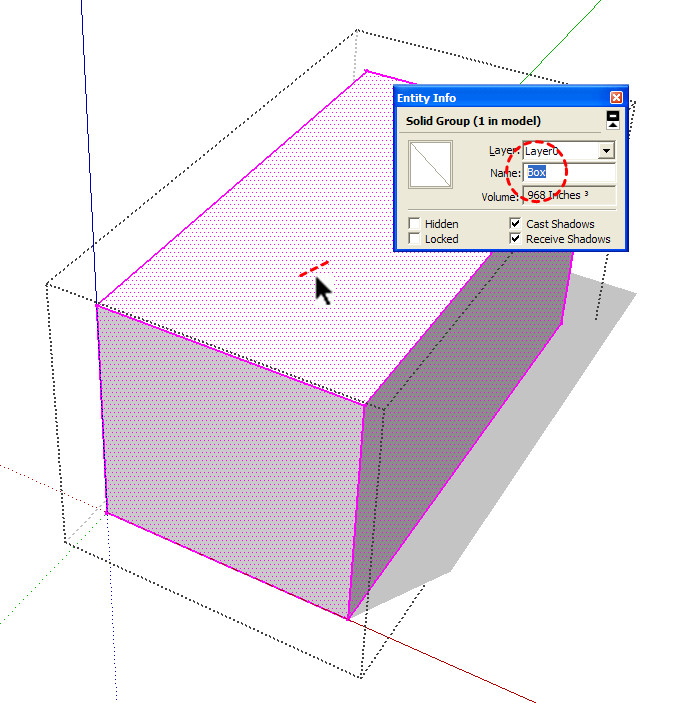
To convert the 3D surfaces and edges of the extrusion into a piece that’s ready for assembly, you need to immediately group and name the box as a distinct object – even before finalizing its shape. To group the extrusion as a single object, triple click any of its surfaces, and select Group from SketchUp’s Edit menu. When you use shortcut keys, the fabricating process is really fast: 1) Triple click; 2) Key-in “g”; and 3) Name the group in the Entity Info box. (See this video for setting up ShortCuts ).Insitebuilders - SketchUp Groups
Groups are quick to make and easily modified with the Edit Group command (or double click). They also save a lot of time when there are only a few instances of the group in the model. For example, use groups for a model base, concrete footing, or part of a building system (See this video to review groups).Insitebuilders - Building Foundation Groups
In SketchUp, you can also make any piece of an assembly a component, but avoid components unless you know you’re going to be using a lot of pieces throughout a large construction model – for example as an array of studs, joists, or the steel in a moment frame.Insitebuilders - Piece-based construction
Components reduce calculation time as you move in and around large assemblies with hundreds of similar pieces. They are also important when an object is going to be saved into a stock library folder. To make and save a component, right click a group and select Make Component, then right click again and select Save As to store it in a file on your computer.  

Component storage
Even a simple construction model uses a lot of the same standard pieces. That means once a piece is manufactured you can save it so it’s ready for assembly in a new model. In other words, you can add to your collection with every model you build. You can also Save As any piece as a component from any another construction model -- hundreds are available to save from the models found in our books alone.
Insitebuilders - SketchUp Component Library 

Scale to fit
Groups can be easily edited in SketchUp, but changes get complicated when you start modifying components. To make things quick and simple, resize components with the Scale tool instead of editing each as a unique piece. For example, framing members can be resized to fit different lengths along a single axis without affecting other copies.

This saves both the time it takes to make a unique component and the confusion that comes with having several minor variations of the same component. Even a few unique components are cumbersome and have little value in construction modeling.

If you need to change a component and only want a few copies of the new version, its much faster to Explode the component and immediate Group and rename it as you build a model. Using shortcut keys again: 1) Select the component; 2) Key-in “e” to explode; 3) Key-in “g” to group; and 4) Rename the new group in the Entity Info box.
 
Stay organized
Of course, construction modeling only works for builders who know how a building actually goes together in the real world – piece by piece. And just like the real-world, when assembly is smooth and everything is coming together quickly, it’s tough to slow down and keep the jobsite and materials organized. At the same time, the importance of a well organized construction model is exactly like a well organized construction project.
Insitebuilders - SketchUp Outliner
As such the SketchUp Outliner acts as both a management tool and a materials list. When the pieces are grouped and named in categories (concrete block, rebar, joists, blocking, and subflooring), they can then be nested into assemblies (stem wall, floor, wall, roof framing, building systems), and these assemblies can then be grouped according to phases or sequences or further subdivided into subcontracts.

This means the pieces in the Outliner can be controlled, counted and correlated to a spreadsheet or schedule. In other words, the construction model can be used to generate materials lists, illustrate parts of the assembly, or animate sequences as slides or videos to communicate the construction process.
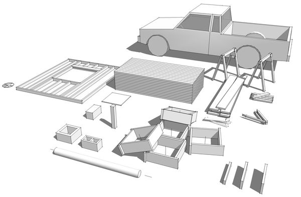
Insitebuilders - Staging the Construction Model
Most important, no piece or assembly is ever lost. The model can be deconstructed, resized, and modified for every new project that comes along. The result is a very effective management and marketing tool. One that clearly demonstrates what your company can and will do in an increasingly competitive construction industry. .