Thursday, January 16, 2014

Part 11: Foundation; Footing Reinforcing

(Introduction, Syllabus, 1.Prelims, 1-4Precon, 2. Excavation, 3.Foundation, 4.Framing, 5.Roof, 6.Close, 7.MEP, 8.Finish)

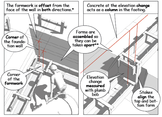
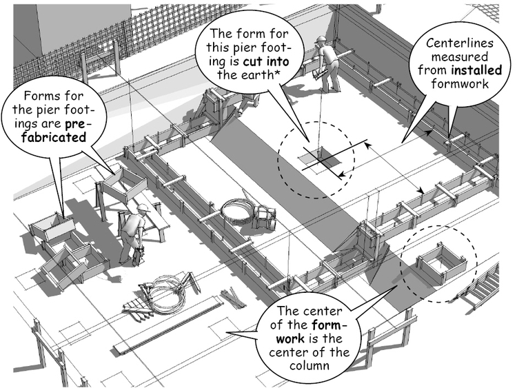
Specialty contractors use reusable forms for their foundations, but for most small projects almost any skilled carpenter can quickly layout and assemble the formwork for a foundation footing.

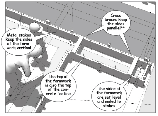
In this example, the footing formwork is assembled with standard lumber that will be reused in the floor and wall framing illustrated later in Phase 4.
Foundation Phase – Insitebuilders

Pier work
If soil conditions are right, the footings can also be cut directly into the soil as shown for the pier footing on the excavated shelf in the illustration above.

Forms for the rest of the pier footings are prefabricated on site so that they can be centered on the string line intersections marking the column locations, or positioned with a tape measure from the perimeter formwork. The center of the pier footing is the center of the column load coming from above.
Foundation Phase – Insitebuilders
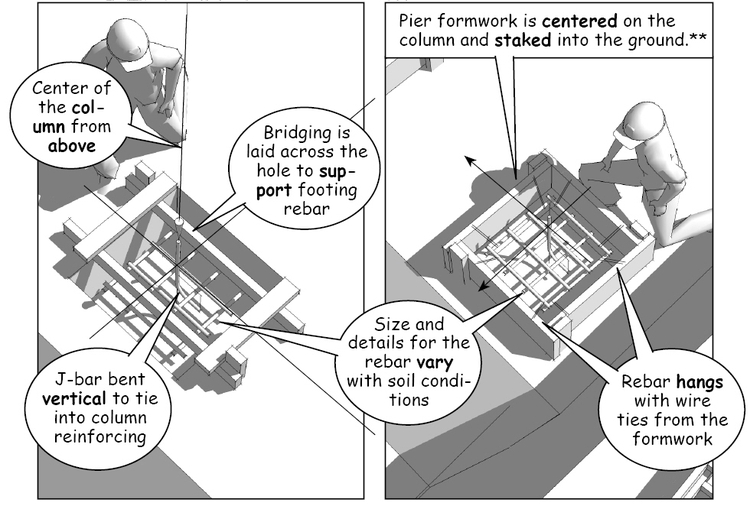
Bridging is used to locate and suspend the concrete reinforcing (rebar) across the top of the open earthen formwork, or from the sides of the prefabricated forms.

For heavily reinforced foundations, some contractors prefer to use light weight plastic “chairs” to hold the rebar up off the floor of the excavation (See Craig’s Concrete Specialties). The size and location of the reinforcing varies with soil conditions and the weight to be distributed over the undisturbed surface of the excavation.

Quality control 
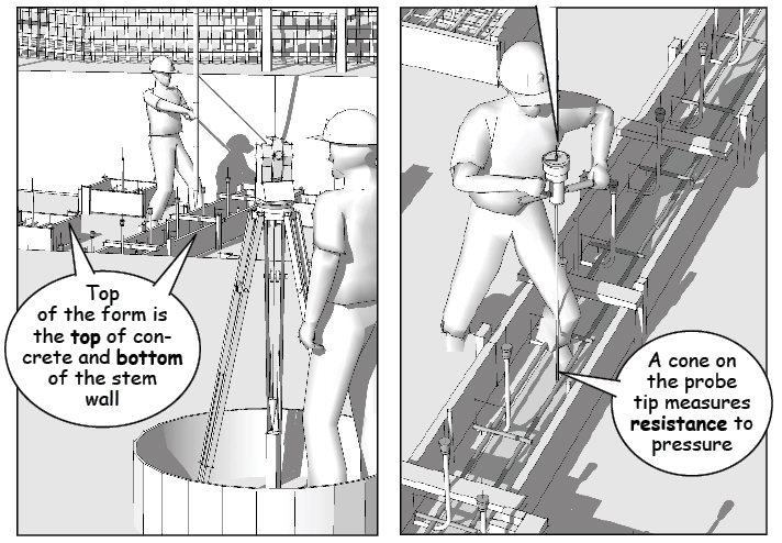
It’s important to check the location and elevations of the footings for accuracy, as well as test soil density to make sure it meets the original engineering specifications. Loose or disturbed soil will sink or compress under the weight of the building.
Foundation Phase – Insitebuilders
Depending on building type and local conditions, some building departments will require certification for the location of the footing, along with penetration test results verifying soil density before authorizing concrete placement.

The workpoint is again the primary reference to check the layout and vertical elevations of the footings. It’s easy to see how a level and accurate excavation minimizes unforeseen material and labor costs for all future construction.  

Continuous reinforcing
Standard lengths for rebar are 20 feet, with diameters measured according to increments of 1/8”. In other words, a #4 bar is 4/8” and a #5 bar 5/8”. This means the rebar must be cut and bent in the field to fit in the formwork using a hydraulic tool (similar to this one supplied by Southern Tool).
Foundation Phase – Insitebuilders 
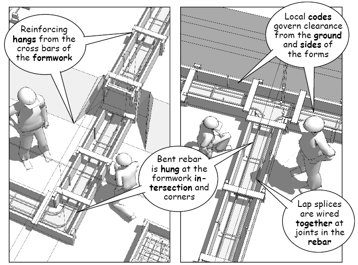
Crossbars are installed to keep the formwork rigid and suspend the rebar. The steel reinforcing is tied to keep it away from the sides of the formwork and up off the ground. Again, chairs or similar spacers may be easier for some builders to install.

Clearances from the ground and sides of the formwork are necessary to protect the rebar and distribute the loads on the foundation once the concrete has cured.
Foundation Phase – Insitebuilders 
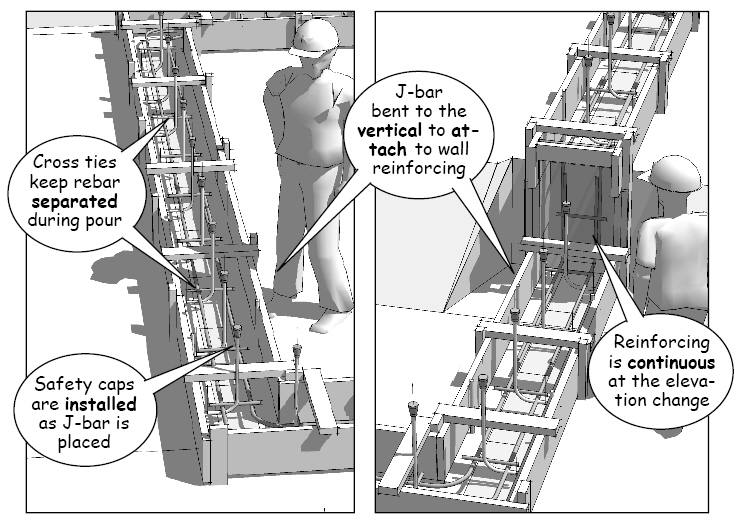
The rebar must also be continuous at all intersections and around corners because any gap or break in the length may result in settlement cracking once the footing is under load.

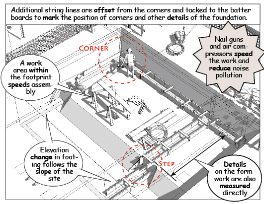
Special attention is also required at any step or change in the footing elevation. Concrete stem walls are formed to fit this step, but for a masonry stem wall, the step should be located so that it fits standard masonry dimensions.
Foundation Phase – Insitebuilders
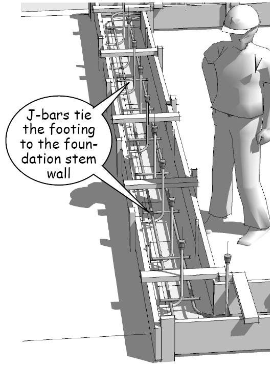
As you’ll see in a later phase, the stem walls require embedded vertical J-bars to tie reinforcing within the wall to the footing after the concrete is ready for the next step in the foundation’s construction.  
.
.(To be continued…) 

--------------------------- 
The material presented in this series has been taken from our book, “How a House is Built: With 3D Construction Models” The book includes annotated illustrations, captioned text, videos, models, and the 2D Preliminaries. 

 insitebuilders.com  
www.insitebuilders.com  
.

Tuesday, December 17, 2013

Part 10: Foundation; Footings

(Introduction, Syllabus, 1.Prelims, 1-4Precon, 2. Excavation, 3.Foundation, 4.Framing, 5.Roof, 6.Close, 7.MEP, 8.Finish)

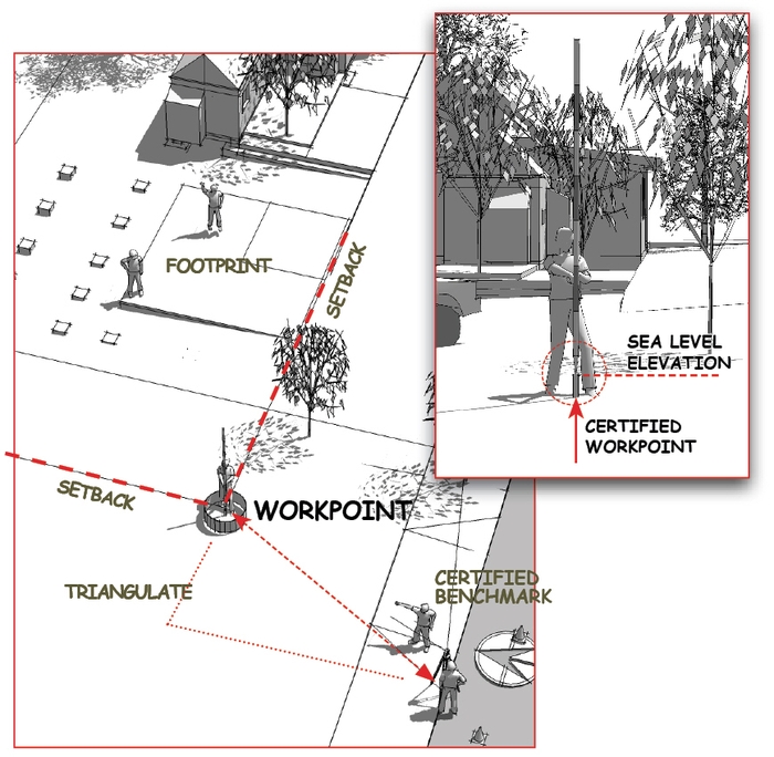
The string lines are a quick reference and good enough for most projects, but experienced builders will use a transit level to cross check the layout of the foundation formwork based on vertical and horizontal distances and triangulated offsets from the workpoint.
Foundation Phase – Insitebuilders
In dense urban areas and zero lot line developments, a licensed surveyor is required to certify the location and depth of the foundation as a condition of the building permit. Zero lot lines occur when zoning restrictions allow construction right up to the property line.  

Concrete Formwork 
For some buildings, concrete is placed directly into a trench cut into the soil using the string lines as a reference. This method is commonly used for the perimeters and bearing walls of a slab or monolithic foundation.

For buildings supported by piers and continuous stem or basement foundation walls, spread footings are used to distribute the weight of the building to undisturbed soil.Foundation Phase – Insitebuilders
General contractors hire subcontractors who specialize in foundations to install these footings. As masons or concrete workers, they clamp together reuseable forms, place the rebar and concrete, then disassemble the forms for their next job as soon as the concrete begins to set.
Foundation Phase – Insitebuilders
In contrast, hands-on builders assemble the footing formwork using standard lumber, setting aside the material for reuse in other parts of the building as blocking or non structural framing once the forms are stripped and cleaned.

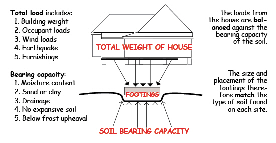
The depth and size of the footing depends on the weight and total load of the building. Dimensions will vary with soil bearing capacity, moisture content, and in some regions the soil frost line.

Bearing capacity and soil
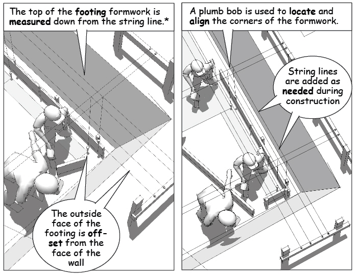
Because the footing is designed to distribute the bearing load from a column or stem wall above, it is offset so that the footing itself is centered on that load. In other words, the center of the wall or column above sits over the center of the footing (see the wall section in the previous post).
Foundation Phase – Insitebuilders
Centering the load in this way means the width of the footing extends out from both sides of the wall above. This means the outer portion of the footing extends beyond the face of the finished wall.
Foundation Phase – Insitebuilders
Technically, the footing might cross a setback line, but since it is below ground, it is most often ignored by building officials. However, when the footing lies against a zero lot line with no setback, the spread footing must be engineered so that the entire foundation remains within the property boundaries.

(To be continued…)

---------------------------  
The material presented in this series has been taken from our book, “How a House is Built: With 3D Construction Models” The book includes annotated illustrations, captioned text, videos, models, and the 2D Preliminaries. 
How a House is Built - insitebuilders.com
.

Tuesday, November 12, 2013

Part 9: Excavation: Quality Control

(Introduction, Syllabus, 1.Prelims, 1-4Precon, 2. Excavation, 3.Foundation, 4.Framing, 5.Roof, 6.Close, 7.MEP, 8.Finish)

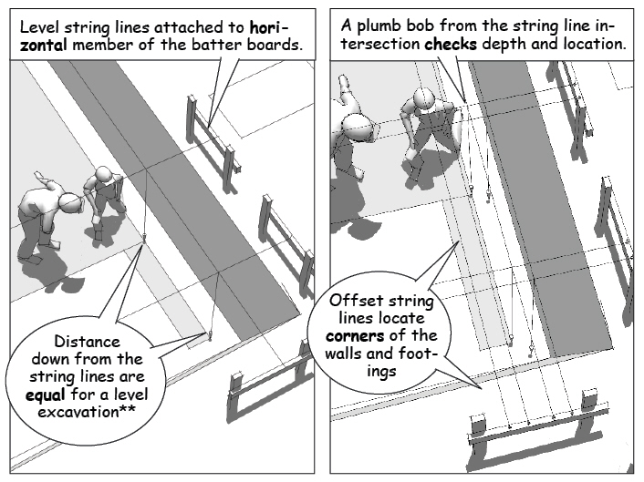
The horizontal member of all the batter boards should now be at the same elevation above sea level. This means the string lines attached to these batter boards can be used as a vertical reference to check the depth of the cut, in addition to locating the critical corners and bearing points for the foundation.
Excavation Phase – Insitebuilders 
Checking the depth of the cut
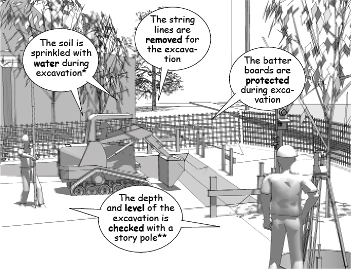
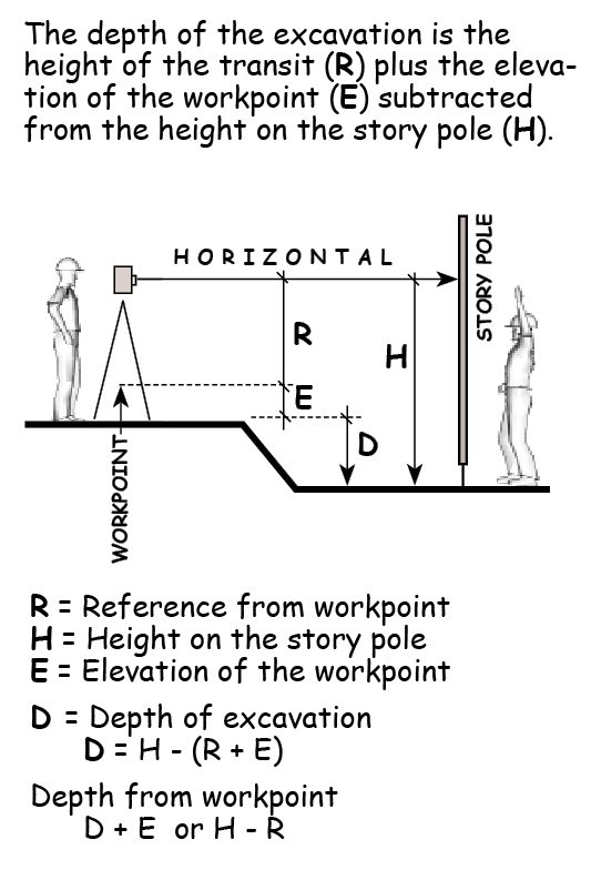
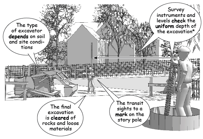
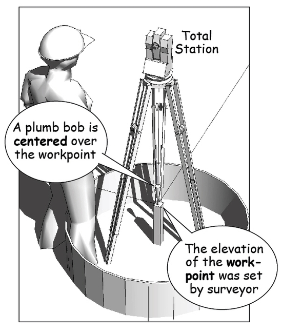
To save time, most builders use a fixed or transit/level to monitor progress and control the quality of the excavation. This survey instrument is set up over the workpoint so its scope remains level through 360 degrees of rotation (see this Tom Duffy video).


Excavation Phase – Insitebuilders
Since the height above the workpoint is now constant, the scope can be aimed at a surveyor’s story pole, first to get an elevation for the existing grade at that point, then to check the depth of any cut by calculating the relative measurements on the story pole.
Excavation Phase – Insitebuilders
The idea is to avoid taking out more material than is absolutely necessary to comply with the requirements for the foundation on of the construction drawings. Removing too much material means it would have to be replaced as backfill or transported off the site an extra cost.  

The foundation layout 
The size and depth of the cut is based on the requirements specified on the construction drawings. These dimensions are shown as a sea level elevation on the civil engineering drawings and transferred as a reference zero point – usually set as the top of the finished floor.
 Excavation Phase – Insitebuilders
A typical wall section shows the depth of the excavation from this zero point to the relative heights of foundation stem walls, footings, and the total thickness of the structure supporting the finished floor. The height of the structural framing, finished grades, walkways, and other site work are all referenced from this common zero point.
Excavation Phase – Insitebuilders
A plumb bob is used to transfer the location of the walls and bearing points from the string line intersections to the floor of the excavation and position the foundation formwork. The depth of the excavation and the top of the formwork are then measured vertically from the string lines, and the corresponding horizontal members of the batter boards.
Excavation Phase – Insitebuilders
Important is that an accurately placed and level excavation sets the stage for masons and concrete workers, so that they can build the foundation according to their original contract estimates. If the cut is misplaced, too deep, or irregular, it means additional labor and materials, schedule delays, and a possible change order.

(To be continued…)  

---------------------------
The material presented in this series has been taken from our book, “How a House is Built: With 3D Construction Models” The book includes annotated illustrations, captioned text, videos, models, and the 2D Preliminaries.


Tuesday, October 15, 2013

Part 8: Excavation: Construction Layout

(Introduction, Syllabus, 1.Prelims, 1-4Precon, 2. Excavation, 3.Foundation, 4.Framing, 5.Roof, 6.Close, 7.MEP, 8.Finish)

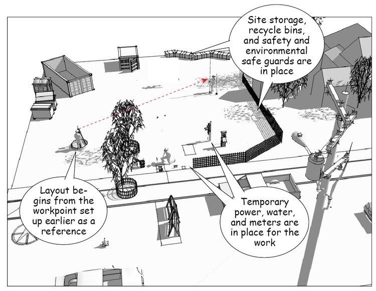
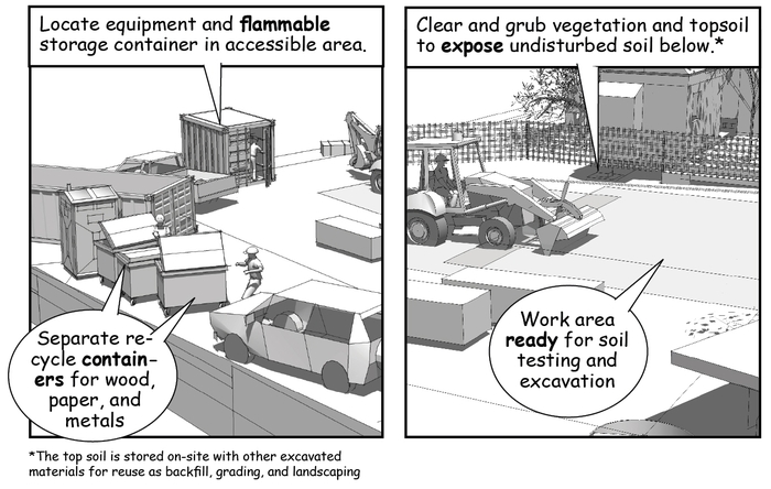
In an ideal world, construction starts once the general contractor has the site ready with temporary utilities, storage, recycling bins, and safety and environmental safeguards in place.
Excavation Phase – Insitebuilders

Layout foundation corners
An accurate layout is important, especially in high density areas when the building is near a setback or property line, because its final height and location must often be verified by a licensed surveyor prior to being granted a certificate of occupancy.
Excavation Phase – Insitebuilders
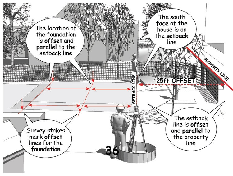
The layout begins by positioning a surveying instrument directly over the workpoint that was located during start-up planning. As noted earlier, this workpoint is a field reference for both an elevation above sea level and a precise location on the jobsite that corresponds with the elevations and dimensions shown on the construction drawings.
Excavation Phase – Insitebuilders
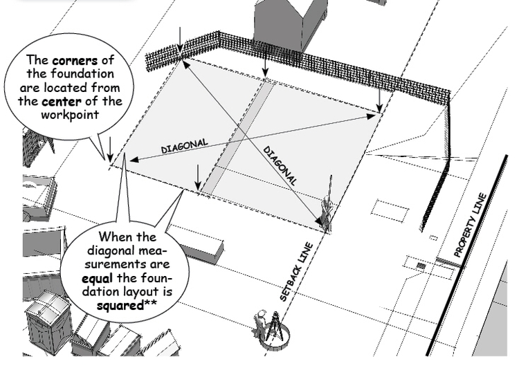
The sitework, foundation corners, floor and roof heights, are all located from this workpoint using either the geometric computations built into surveying instruments, or by triangulating the bearings and distance to the corners, framing, or ridgeline during construction. (See GIS surveying instruments).
Excavation Phase – Insitebuilders
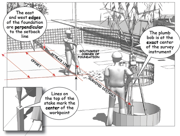
For straightforward foundations on an open site, most builders would simply measure parallel offsets from a predetermined reference line sighted along the setback or property corners.
Excavation Phase – Insitebuilders
Measurements along the length of the reference line from the workpoint are taken from dimensions specified on the construction drawings. A light weight builder’s transit/level is then repositioning over stakes located at critical distances along that line to layout the walls or objects perpendicular to, or along arcs left or right of, this reference.
Excavation Phase – Insitebuilders
The layout is then checked with optical lasers, GPS, or by diagonal field measurements to square up the foundation corners.  

Setting batter boards
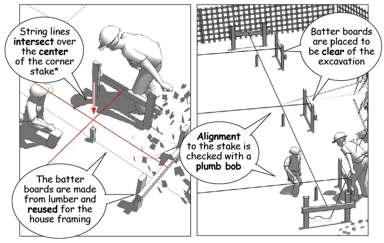
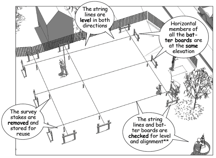
Once the corner stakes are set and checked for accuracy, string lines are extended from temporary batter boards placed well outside the area to be excavated. Important is that the horizontal member for each of these batter boards is level, and that they all share the same elevation as referenced from the workpoint.

The batter boards allow builders to carefully position string line intersections over the center marker on the corner stakes. They will also be used to gauge the depth of the excavation and the height of the foundation walls and footings as the work continues.
Excavation Phase – Insitebuilders
The string lines are tied to nails on the upper surface of the batter boards. They locate the outside face of the foundation walls and any interior stem walls, special conditions, or changes in elevation within the excavated perimeter.
Excavation Phase – Insitebuilders
Once the string lines are checked and labeled, they can be untied and set aside in order to clear the area for the equipment needed to start the excavation. The strings can then be quickly reset during the excavation to check progress, verify the depth of the cut, and re-establish the foundation corners.
.
(To be continued…)  
.
---------------------------

How a House is Built - Insitebuilders  
The material presented in this series has been taken from our book, “How a House is Built: With 3D Construction Models” The book includes annotated illustrations, captioned text, videos, models, and the 2D Preliminaries.
.

Tuesday, September 17, 2013

Part 7: Preconstruction: Installing Construction Utilities

(Introduction, Syllabus, 1.Prelims, 1.5Precon, 2. Excavation, 3.Foundation, 4.Framing, 5.Roof, 6.Close, 7.MEP, 8.Finish)

Site utilities for this project include their installation for the new house as well as connection fees and monthly payments for temporary power, water, and any other services necessary to complete its construction.  

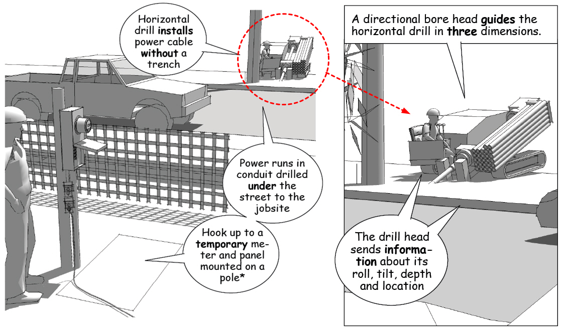
Installing temporary power
Power connections are made to utility lines that extend from a transformer capable of serving the building. For light residential construction, transformers are installed to supply several houses through metered connections that are turned on by the utility company that will be supplying the power.
Preconstruction Planning - Insitebuilders
Overhead supply lines drop from raised main lines strung across roads and public areas. Underground service must be installed in a protective conduit or a reinforced heavy duty cable that is then inspected for compliance with detailed specifications prior to burial.
Temporary Power - Preconstruction Planning - Insitebuilders
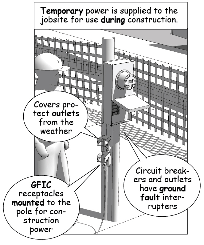
For the construction, a temporary power pole is placed on site according to the site utilization plan (SUP). The size, location, and grounding for the metered connection must again comply with local electrical codes before it can be connected.

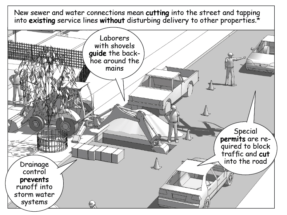
Street cuts for utility installations
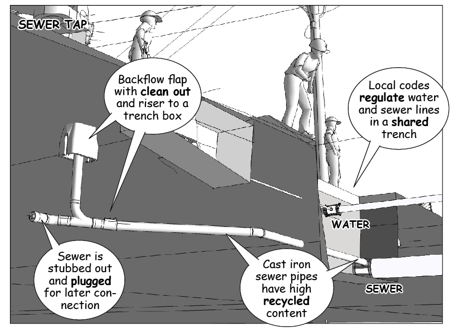
In some cases, utility taps must be made to manholes or underground service boxes that require a street cut. This is almost always the case for sewer, water, and gas connections.
Street Cu -  http://insitebuilders.com /blogimages/Blog130913/03StreetCut.jpg
The extent of the work necessary to tap into utilities under a public right of way depend on the preparation needed to protect vehicular and pedestrian traffic, the location and depth of the mains, and the cost of repairing the road and other public property following the requirements local officials.Water Sewer Tap - Preconstruction Planning - Insitebuilders
In some cases certified subcontractors or special permits are required, drawn by the contractor to show details for roadwork, curb cuts, and excavation because of safety concerns for injury during and after the installation. For example, shoring is required in unstable soil or for trenches more than 5 feet deep, along with railing and falsework for sidewalks, and silt barriers for erosion control.  

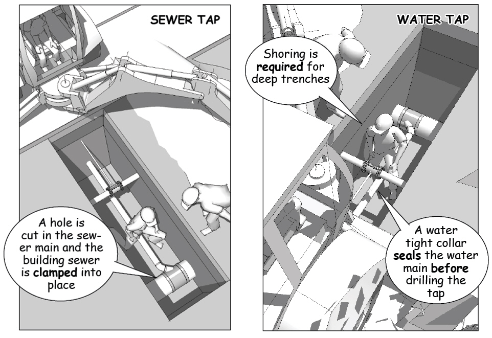
Tapping into the sewer and water mains 
Because of existing hydraulic pressures, special precautions must be made to tap into an active utility main and avoid interrupting service to current customers or damaging other utility lines during the installation. Hot taps like these for major constructions are made by specialists using a special clamp, bolted or welded onto the sewer or water main.
 

The clamp has a water tight collar and is engineered to seal the mainline. Once in place, the drill or cutting head is mounted to a series of valves that are then reset to remove the cutter and any debris before opening the flow to or from the building. The process can be competitive as you can see here.
Water Tap - Preconstruction Planning - Insitebuilders
Once the taps have been completed, shut off valves, back flow protectors, and meters are installed. The connections are then inspected and recorded, and the area backfilled and refinished according to public works specifications.

Site Utilities - Preconstruction Planning - Insitebuilders
Important is that the street, sidewalks, and any areas damaged by the work must be repaired or replaced. In most cases this means new sidewalks, curbs and gutters, as well as landscaping and vegetation that must be listed as line items in the costs shown on a construction contract.

Preconstruction Planning - Insitebuilders  
(To be continued…)

---------------------------  
The material presented in this series has been taken from our book, “How a House is Built: With 3D Construction Models” The book includes annotated illustrations, captioned text, videos, models, and the 2D Preliminaries. 
 Insitebuilders - How a House is Built

Tuesday, August 13, 2013

Part 6: Preconstruction: Health and Safety

(Introduction, Syllabus, 1.Prelims, 1-4Precon, 2. Excavation, 3.Foundation, 4.Framing, 5.Roof, 6.Close, 7.MEP, 8.Finish)

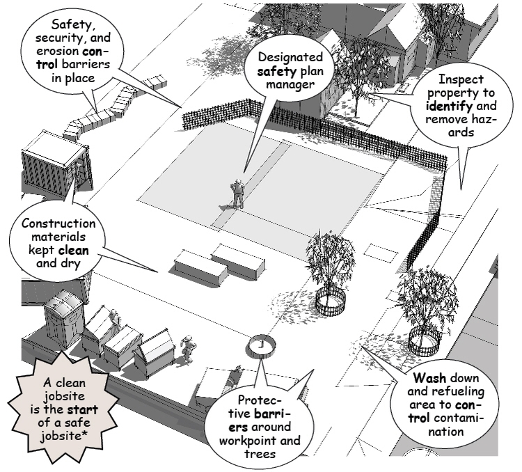
Startup activities begin with risk assessment and safety planning for each phase of the construction, once the workpoint and work and storage areas are determined on the SUP.  

Construction Health and Safety Plan
Skilled managers anticipate potential hazards by assessing risks for each phase of the construction. A safety plan is then drawn to identify challenging actions during the construction process, utility locations, potential hazards, environmental impact, and the location of field tests to determine soil conditions. 
Preconstruction Planning - Insitebuilders
On a large project, a safety plan manager is appointed to continually review operational risks, maintain safe practices, assess environmental impacts, and keep everyone on the jobsite aware of the importance of regulating health and safety.
Preconstruction Planning - Insitebuilders
Written safety plans are usually required by construction insurance carriers and are important to document pre-emptive planning in the event of an injury, subsequent law suit, and worker’s comp claims against the contractor and owners.

Startup Utilities for the Construction
Once setbacks and work areas have been generally identified, utilities are located and marked for connection. Power is needed immediately to construct formwork and falsework to reinforce existing structures. Water is necessary to keep workers hydrated, dust control, and equipment wash-off.
Preconstruction Planning - Insitebuilders
Special concerns include overhead power lines, underground utilities, soil contamination and containment, water and erosion, and natural drainage patterns during construction.
Preconstruction Planning - Insitebuilders

Field Testing
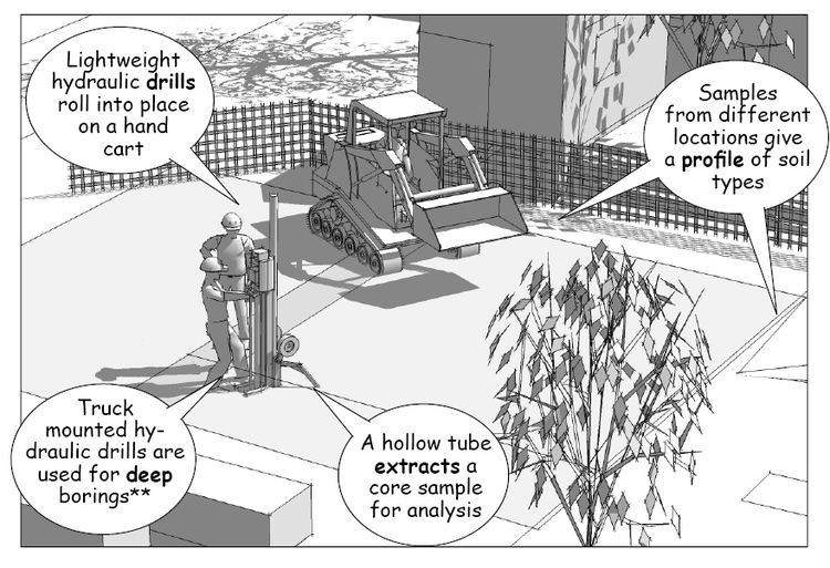
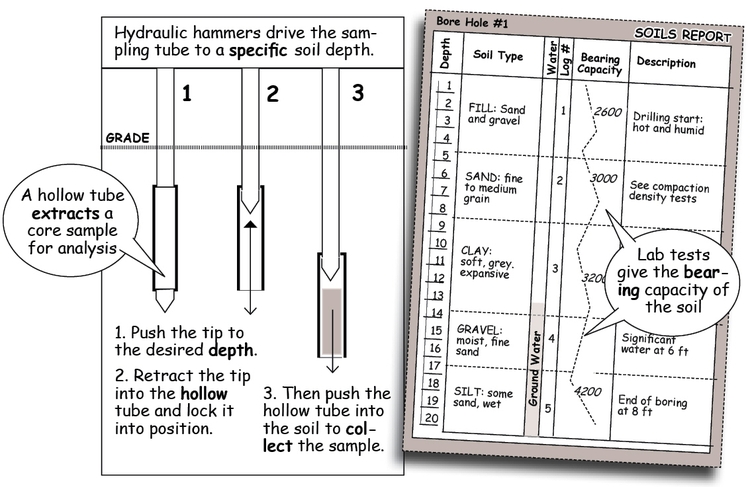
Soil tests determine bearing capacity and moisture content. Tests look for clay that could push up on the foundation and utility lines, as well as sandy soils that could shift or sink under the weight of backfill or the building.
Preconstruction Planning - Insitebuilders
These tests are important to construction planning because they disclose potential problems not only with the foundation for the building, but for slump and sluff factors that may require shoring for utility trenches and the walls of the building excavation.
Preconstruction Planning - Insitebuilders  

(To be continued…)
 
Preconstruction Planning - Insitebuilders
---------------------------  
The material presented in this series has been taken from our book, “How a House is Built: With 3D Construction Models” The book includes annotated illustrations, captioned text, videos, models, and the 2D Preliminaries.
Preconstruction Planning - Insitebuilders

Monday, July 15, 2013

Part 5: Preconstruction: Marshalling and Staging

(Introduction, Syllabus, 1.Prelims, 1-4Precon, 2. Excavation, 3.Foundation, 4.Framing, 5.Roof, 6.Close, 7.MEP, 8.Finish)

Preconstruction planning includes the environmental impact of the construction on neighbors, public safety, and noise-light-smoke-dust pollution and often required as a special condition for a building permit.  

Lines in space 
 Construction planning starts by physically transferring the lines and dimensions shown on a set of construction drawings to the actual real-world site conditions.
Preconstruction Planning - Insitebuilders
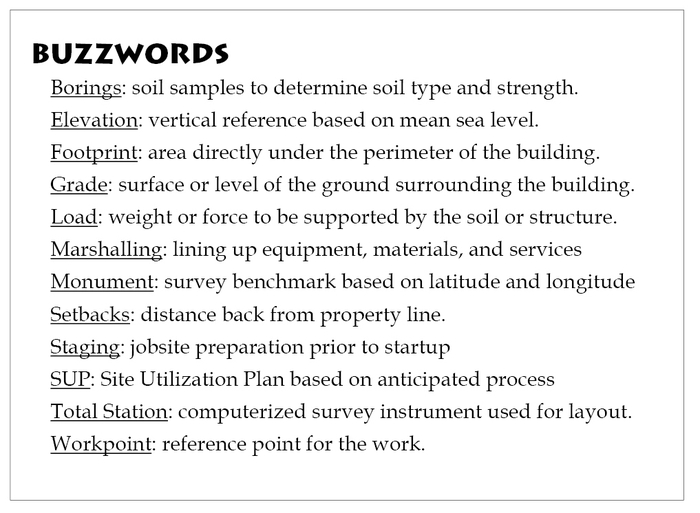
This is done with surveying instruments designed to locate points in space by triangulating distances from a workpoint. This workpoint is derived from geographic monuments and acts as a three-dimensional reference during excavation, foundation, framing, and site work.

Site Utilization Plan
The workpoint is also the basis for a site utilization plan (SUP) drafted by the contractors. A SUP is used to think through each phase of the construction, identifying changing work areas, required falsework, safety concerns, site storage, environmental protection, access controls, parking, and traffic.
Preconstruction Planning - Insitebuilders
The plan itself can be a rough drawing, collaborative white board sketch, or a screen-shot from a simple three-dimensional model.
 Preconstruction Planning - Insitebuilders
The SUP is also the basis of a safety plan, startup site preparations, marshalling, support services, storage, staging, layout areas, and clearing and grubbing in preparation for excavation, grading, and site utilities.
Preconstruction Planning - Insitebuilders 
Once the site is prepared, the building’s footprint is laid out from the workpoint and used to locate soil borings to test and analyze the strength of the soil under the foundation. These borings determine ground water, bearing capacity, and soil type and are drilled early in the construction process in order to identify structural changes that might affect the depth or dimensions of the excavation.
Preconstruction Planning - Insitebuilders

(To be continued…)

---------------------------  
The material presented in this series has been taken from our book, “How a House is Built: With 3D Construction Models” The book includes annotated illustrations, captioned text, videos, models, and the 2D Preliminaries.
How a House is Built - Insitebuilders.com