Wednesday, September 16, 2015

Part 31: Intersecting Hip Roof

(Introduction, Syllabus, 1.Prelims, 1-4Precon, 2. Excavation, 3.Foundation, 4.Framing, 5.Roofing, 6.Shell, 7.MEP, 8.Finish)
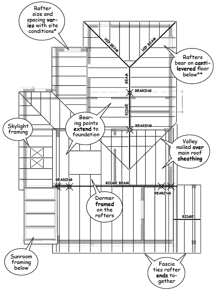
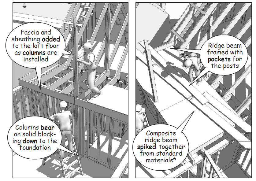
An intersecting ridge beam is framed into the rafters on the north side of the house. This beam is designed as a double cantilever, extending out over two columns to support loads at each end.
Cantilevered to intersect with the rafters
The intersecting ridge beam bears on columns that carry the roof loads down to the foundation wall. Solid blocking is added between the floor joists under the columns to maintain full bearing.
Framing Phase – Insitebuilders
The cantilever transfers the weight from the roof to the column, minimizing the load on the rafters at the intersection.
Framing Phase – Insitebuilders
The framing members of the composite beams and columns are spiked and glued so that they “sandwich” each other at the rafter connection, similar to a furniture maker’s mortise and tendon joint. This reduces the need for moment connectors, making it possible for the pieces to be bolted together. Framing Phase – Insitebuilders
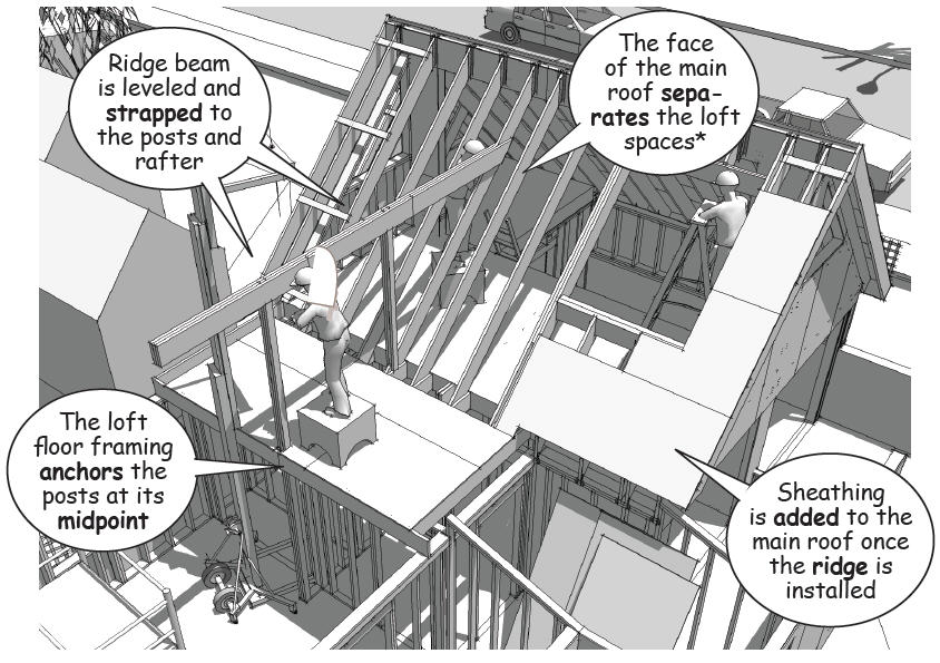
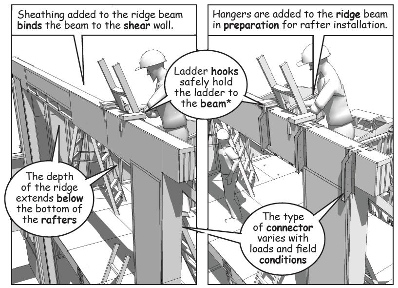
Once the ridge beam is in place, sheathing is nailed to the rafters to strengthen the frame and enclose the loft. 
Cantilevered to support the hip connection
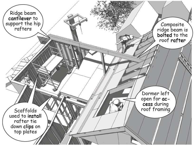
On the opposite end, the ridge beam extends out over a second column to support the hip connection, eliminating the need for a truss or bearing wall at this point.
Framing Phase – Insitebuilders
The cantilever transfers the loads from the hip connections back to the column and down to the foundation.
Framing Phase – Insitebuilders
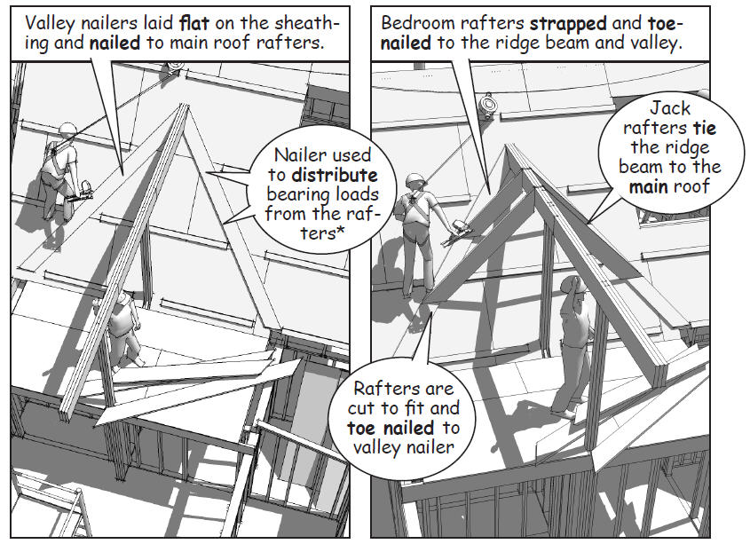
Once the ridge beam is in place, sheathing is completed on the north roof so that “jack rafters” can be connected to sleepers lag bolted into the rafters of the main roof.
Framing Phase – Insitebuilders
Structural clips are used along the ridge beam and the interior bearing walls to counter the uplift loads that occur in the valleys at the roof intersections.
 
(To be continued…)
---------------------------
The material presented in this series has been taken from our book, “How a House is Built: With 3D Construction Models” The book includes annotated illustrations, captioned text, videos, models, and the 2D Preliminaries.

Monday, August 17, 2015

Part 30: Setting Rafters and Sheathing

(Introduction, Syllabus, 1.Prelims, 1-4Precon, 2. Excavation, 3.Foundation, 4.Framing, 5.Roofing, 6.Shell, 7.MEP, 8.Finish)
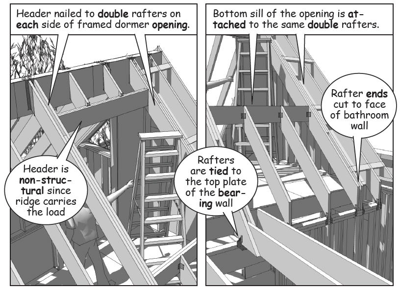
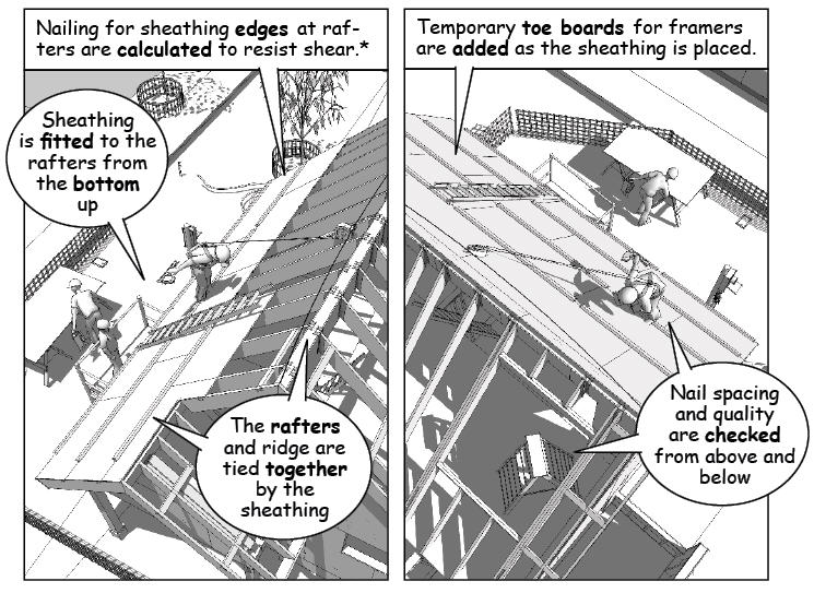
Roof sheathing is added to stiffen the steeply pitched roof against lateral loads caused by wind and earthquake. An opening for a dormer on the north side of the roof is left open and will be framed after the intersecting hip roof is completed.
Framing the opening for the dormer
The opening allows carpenters to stage tools and equipment on the loft floor and have direct access to the work for the intersecting roof.
Framing Phase – Insitebuilders
The framing for the dormer is framed similar to the opening in a wall, with a header, sill, and reinforced jambs to carry loads down from the roof and walls.
Framing Phase – Insitebuilders
Short rafters are clipped to the ridge beam and the interior bearing wall to counter uplift loads from the dormer once it is in place.
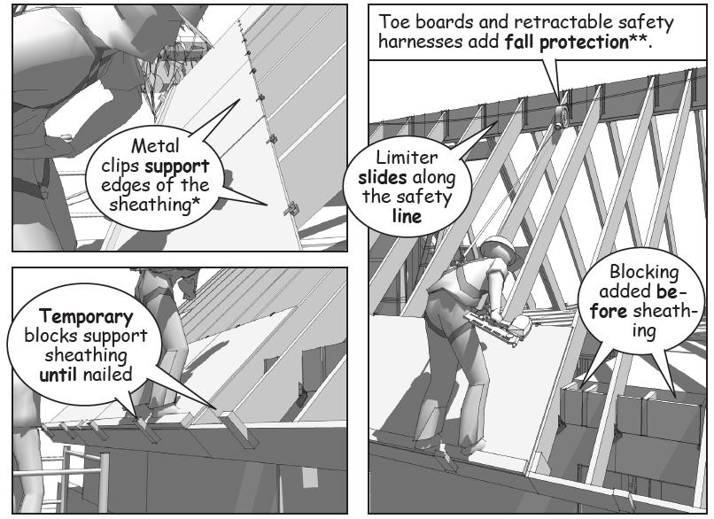
Roof sheathing stiffens the roof framing
The edges of the sheathing are supported by structural clips inserted between the rafters along the horizontal joints. These clips stiffen the edges against long term loads from weather and dead weight of the roofing.
Framing Phase – Insitebuilders
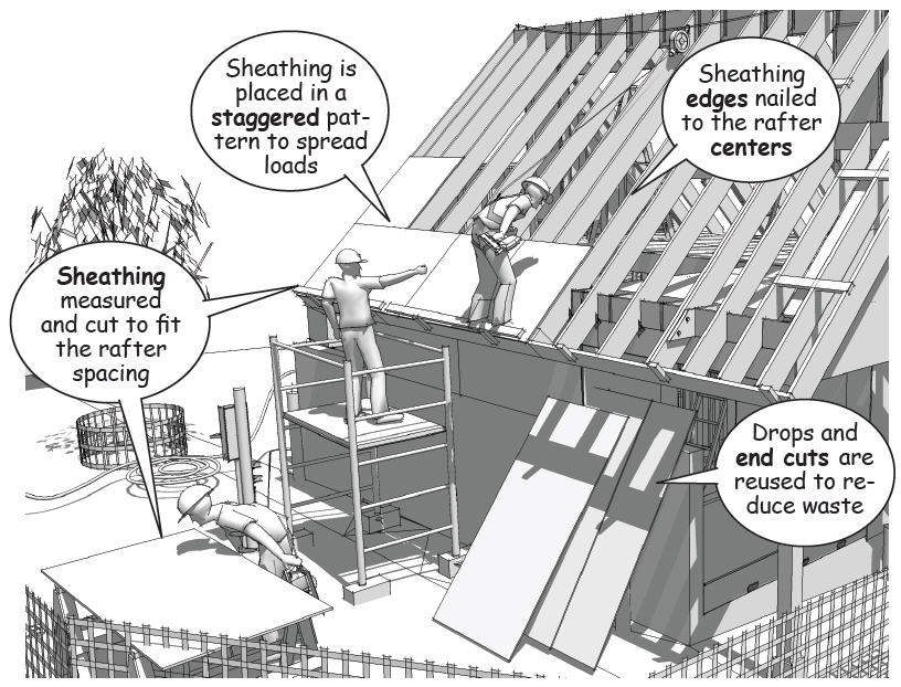
The sheathing is placed in a staggered pattern to minimize continuous joints and distribute the roof loads evenly across the rafters.
Framing Phase – Insitebuilders
Each sheet is cut to fit the rafter spacing and the edges are nailed following a designated nail pattern. Nail placement and spacing are specified by the engineering calculations and the requirements of local building codes.
Framing Phase – Insitebuilders
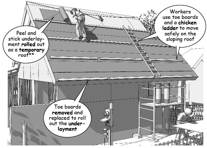
Safety lines and harnesses are not always required by residential codes for single story construction, but the added support makes it possible for carpenters to move quickly across the roof and repel along the roof edges.
Framing Phase – Insitebuilders
Toe boards and chicken ladders give the carpenters a better footing and are nailed into the rafters as an underlayment to temporarily waterproof the unfinished framing.

(To be continued…)

---------------------------
The material presented in this series has been taken from our book, “How a House is Built: With 3D Construction Models” The book includes annotated illustrations, captioned text, videos, models, and the 2D Preliminaries.
Insitebuilders.com
.

Thursday, July 16, 2015

Part 29: Setting Rafters

(Introduction, Syllabus, 1.Prelims, 1-4Precon, 2. Excavation, 3.Foundation, 4.Framing, 5.Roofing, 6.Shell, 7.MEP, 8.Finish)

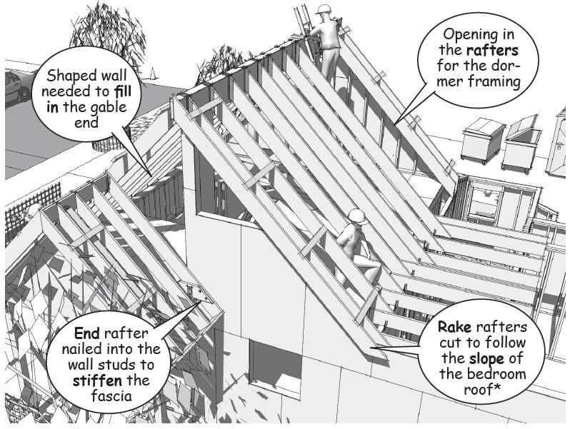
Traditional roofs are framed using rafters that extend from a ridge beam down to the top plates of bearing or perimeter walls. The slope of the rafters shapes both the ceiling and the profile of the house.  

Rafter framing at the main roof 
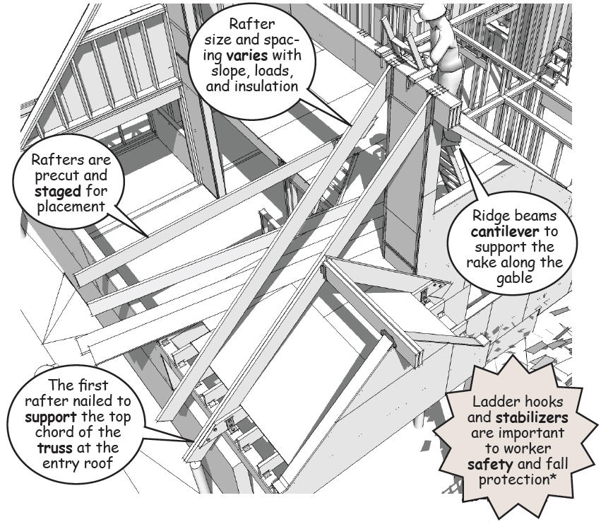
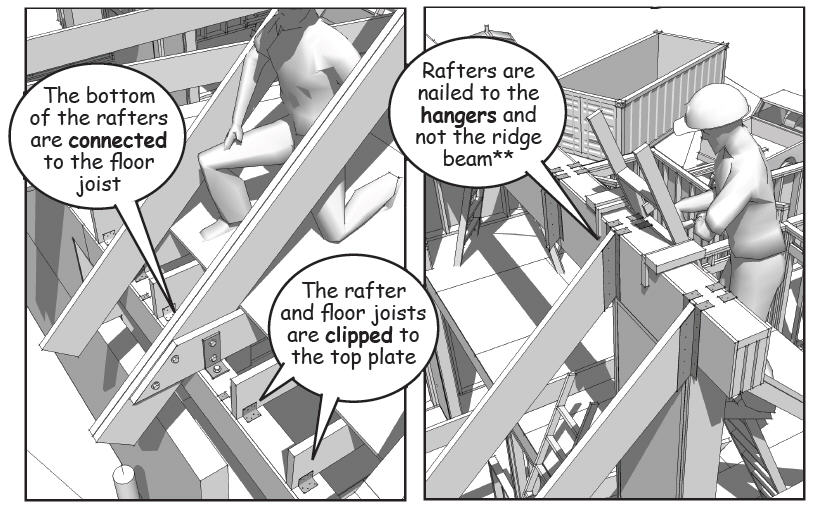
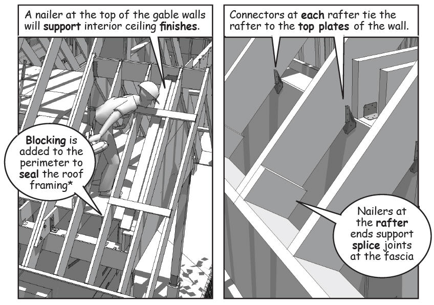
Structural connectors similar to those used in the floor framing are used to tie the rafters to the ridge beam and the top plates of the bearing walls. The connectors counter uplift and lateral loads imposed on the house by wind or earthquake.
Framing Phase – Insitebuilders
The connectors are predrilled according to engineered nailing patterns that prevent over nailing in the field. High strength “joist” nails are used instead of common framing nails to secure the rafters at the connector.
Framing Phase – Insitebuilders
It’s important to tie off or block ladders at the top and base of the work area to prevent falls caused by displacement or slippage. The slope of ladder should be about 75 degrees or approximately one unit horizontal for every four units vertical.
Framing Phase – Insitebuilders
For example a 24-foot ladder should be set out approximately 6 feet at the bottom of the ladder. See safety requirements and hook attachments for construction ladders at www.wernerladder.com .

Outlooks support the rake rafters
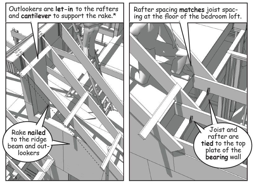
Rake rafters support the overhang at the gable ends of a roof. These rafters extend beyond the face of the perimeter walls and are held in place by outlooks (or outlookers) that are “let in” to the top of the main roof rafters.
Framing Phase – Insitebuilders
The rafters are notched to receive the outlooks so that the top of the outlook is level with the top of the rafter. The outlooks cantilever beyond the face of the wall to support the rake rafters. Outlook spacing depends on the length of the overhang and the wind load requirements of local building codes.

Placing the rafters 
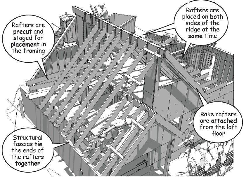
Rafters are precut to match the required slope of the roof. Though structural connectors make it structurally unnecessary, many skilled carpenters prefer to cut bird mouths into the rafter at the bearing points to provide a flat surface for the roof loads.
Framing Phase – Insitebuilders
The end of the rafters cantilever past the perimeter walls to a structural fascia according to the requirements of the overhang. The fascia is structural because they tie the rafters together as a single unit and distribute roof loads to neighboring rafters.
Framing Phase – Insitebuilders
Blocking is added between the rafters at the perimeter wall to prevent fire on the outside of the house from entering the space between the rafters through the soffit.

(To be continued…)

---------------------------
The material presented in this series has been taken from our book, “How a House is Built: With 3D Construction Models” The book includes annotated illustrations, captioned text, videos, models, and the 2D Preliminaries. 
 Insitebuilders.com

Monday, June 15, 2015

Part 28: The Ridge Beam

(Introduction, Syllabus, 1.Prelims, 1-4Precon, 2. Excavation, 3.Foundation, 4.Framing, 5.Roof, 6.Close, 7.MEP, 8.Finish)

The perimeter wall sheathing is completely nailed before roof framing begins. The sheathing stiffens the frame, finalizing bearing points, tie downs, and connectors as a unified structural system in preparation for the roof loads.  

Preparing supports for the ridge beam 
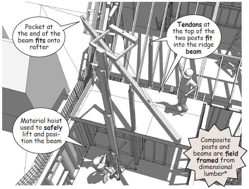
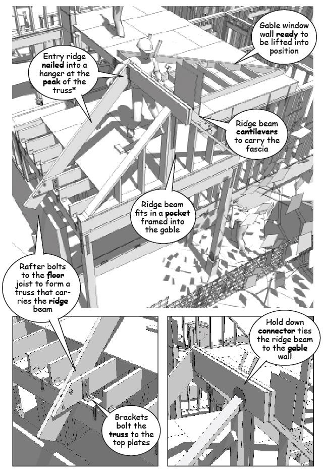
Because of the open ceiling in this example, these preparations also include framing beam pockets into the shear and gable walls that support the main ridge beam. These triangular walls are shaped to follow the slope of the rafters.
Framing Phase – Insitebuilders
The ridge beam bears on vertical extensions of the shear walls and the sheathed gable walls work to resist movement perpendicular to the axis of the roof line.
Framing Phase – Insitebuilders
Note that the shear walls are embedded between the gable walls so that a length of the ridge beam is fixed into position. The upper portion of the shear walls are bolted to the lower wall using tie downs and the structural nailing pattern. The sheathing on both sides of the shear wall transfers lateral loads through the wood frame to the foundation.
Framing Phase – Insitebuilders
Once in place, the roof supports extend from the ridge beam and rafters down through the loft floor to the tie downs at the foundation stem wall. In some cases, steel straps are added to strengthen the moment resistance of the stud walls.

Setting ridge beam
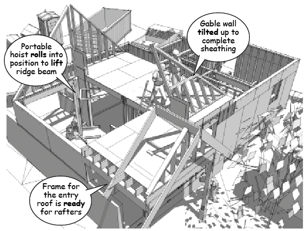
After a final check, the area is cleared of unnecessary tools and materials and the ridge beam is ready to be set in place.
 Framing Phase – Insitebuilders
Options for lifting the ridge beam include a floor hoist as shown in this construction model or a light duty crane similar to those used by sign contractors or tree service companies.
 Framing Phase – Insitebuilders
Overhead safety is again of primary importance. Critical concerns include marking safe zones for workers, a safety observer to watch the lift as the beam is positioned, securing equipment, assessing unusual site conditions, and the experience of the carpentry crew.    


(To be continued…)

---------------------------

The material presented in this series has been taken from our book, “How a House is Built: With 3D Construction Models” The book includes annotated illustrations, captioned text, videos, models, and the 2D Preliminaries. 
  Insitebuilders.com

Saturday, May 16, 2015

Part 27: Final Preparation for the Roof Framing

(Introduction, Syllabus, 1.Prelims, 1-4Precon, 2. Excavation, 3.Foundation, 4.Framing, 5.Roof, 6.Close, 7.MEP, 8.Finish)

Almost all residential roofs are framed using prefabricated trusses rather than more traditional conventually framed ridge beams and rafters. As noted above, truss roofs offer speed and labor efficiency and are designed by truss manufacturers using simple computer programs. The framing members are then prefabricated and delivered to the jobsite to be erected as an interlocking framing system.  

Traditional roof framing
As an alternative, traditional roof framing is field fabricated, maximizing the use of the space under the roof, but it also requires more time and attention to detail than component or truss framed roofs. Engineering is also more complex with roof slopes, spans, and the thickness required for insulation governed by the depth and spacing of framing members.
Framing Phase – Insitebuilders
Traditional framing takes both experience and carpentry skills not often found in production residential construction. It is shown here for educational purposes. Though not difficult to build, this type of construction is best assembled by seasoned builders working for owners who value the space and visual interest of open ceilings and clerestory windows.  

Sheathing stiffens the frame
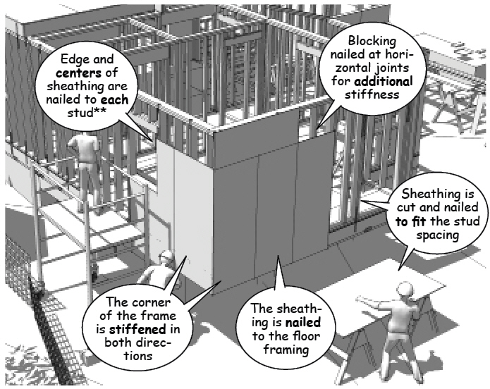
Once the top plates and loft framing are in place, sheathing is added to the outside of the exterior walls to stiffen the frame. The sheathing is nailed to the studs and plates to resist lateral loads and uplift forces from wind and earthquake.
Framing Phase – Insitebuilders
The spacing of nails along the edges and centers of the sheathing varies with the anticipated loads on the structure.
Framing Phase – Insitebuilders
Spacing is determined by engineering calculations that take into account the location, exposure, and wind and earthquake requirements of local building codes.

The geometry of the roof framing
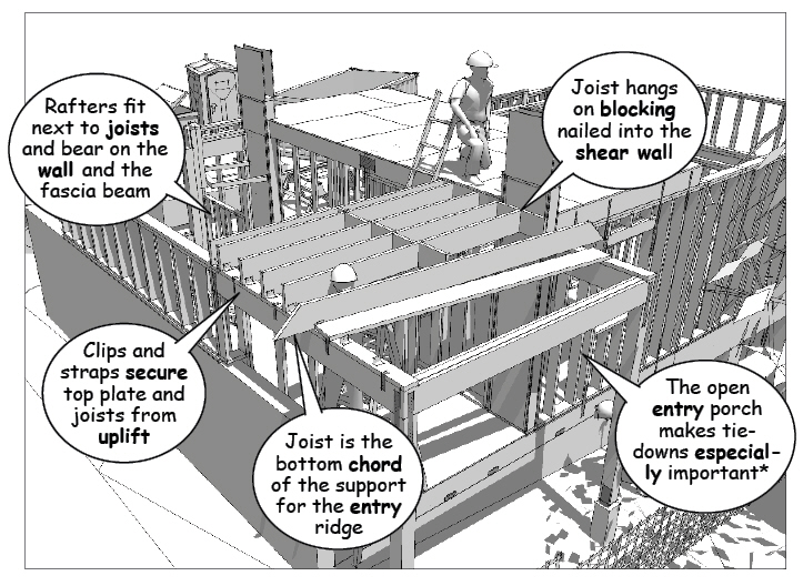
The entry roof is a good example of the geometry of the traditional roof framing method. Note that the framing members form simple triangles with the floor or ceiling joists acting as the bottom chords of the truss and the rafters acting as the top chords or hypotenuse of the triangle.
Framing Phase – Insitebuilders
Shear walls extend from the foundation tie-downs up through the loft floor, all the way to the ridge beam in order to unify the structural system.
Framing Phase – Insitebuilders
Note that fall protection become increasingly important when framing a traditional roof, making safety and careful planning primary concerns during this phase of the construction.    

(To be continued…)

--------------------------- 
The material presented in this series has been taken from our book, “How a House is Built: With 3D Construction Models” The book includes annotated illustrations, captioned text, videos, models, and the 2D Preliminaries.
http://insitebuilders.com

Thursday, April 16, 2015

Part 26: Ready for the Roof Framing

(Introduction, Syllabus, 1.Prelims, 1-4Precon, 2. Excavation, 3.Foundation, 4.Framing, 5.Roof, 6.Close, 7.MEP, 8.Finish)

The availability of standard milled framing materials, structural connectors, and skilled carpenters makes traditional wood framing the obvious choice for most types of residential construction. Wood framing resources include print publications and online information common to an industry of contractors, subcontractors, and material suppliers.

Setting Main Ridge Support
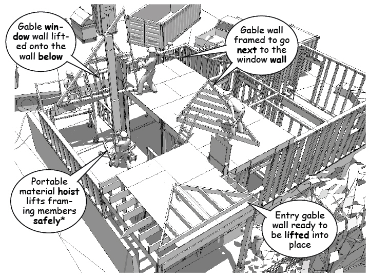
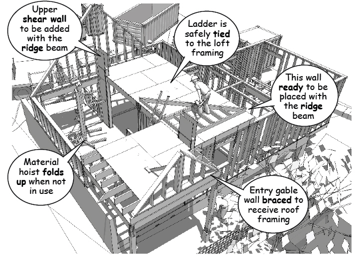
In this example, the ridge beam column supports are built into the gable walls at each end of the open ceiling. The walls are framed so that the sloping top plate matches the height and slope of the roof rafters.
Framing Phase – Insitebuilders
When floor space is limited, the walls are fabricated on the lower level and lifted with a portable material hoist that can be rented from most equipment rental companies, see www.genielift.com for specifications and information.
Framing Phase – Insitebuilders
The gable walls are set to vertical and stabilized with braces or framed into adjacent shear walls so that they remain ridged and in place while the main ridge and header beams are lifted into place.  

Final structural review
The structural integrity of a wood frame house is also easier to inspect and maintain. Most of the connectors and straps required for tie down can be installed after the floor and wall framing are complete. The size and placement of structural connectors varies with location and building loads.
Framing Phase – Insitebuilders
As a structural system, construction began with the installation of securely anchored pressure treated sills. The floor joists are then strapped to the sills and the foundation walls and the walls strapped to the joists. Interlocking top plates then tie the walls together to create a solid structural frame.

Once the walls and connectors are in place and inspected, exterior sheathing is installed with nails spaced according to code requirements. The sheathing further stabilizes the frame prior to beginning the roof framing.

Trusses Roof Framing
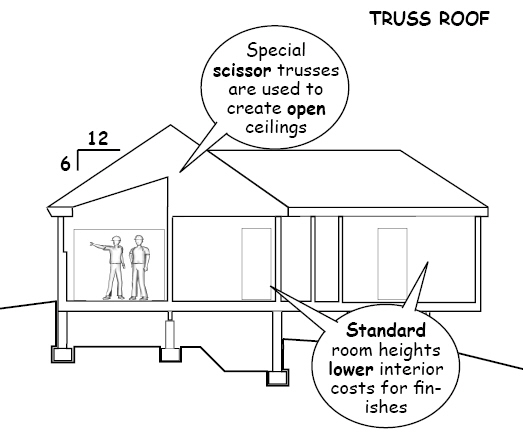
Most residential designers and contractors prefer placing concrete as a slab on grade and installing prefabricated roof trusses because they are much faster and cheaper than field framing a raised floor and open ceiling (see the Wood Council of America research results at www.wtca.org)
Framing Phase – Insitebuilders
  • Prefabricated trusses are economical for large floorplans
  • Less skilled labor required
  • Roof components are computer engineered
  • Simple and fast to erect with a placement plan
  • Quality controlled manufacturing reduces waste
  • On center spacing maximized to reduce materials
  • Long clear spans reducing interior bearing walls
  • Saving in roof labor and material mean less energy consumption
  • Reduced man hours, lower risk, overhead and worker insurance
Conventional Roof Framing
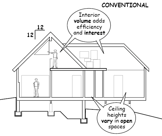
A conventionally framed roof is assembled in the field using off-the-shelf materials. The key advantages are found with smaller houses where reduced labor and faster production have less of an impact and are not a primary consideration (Note that predesign requires careful detailing and coordination with mechanical, electrical and plumbing systems).
Framing Phase – Insitebuilders
  • Best for smaller, custom homes with open spaces and ceilings
  • Framing materials are readily available from lumber suppliers
  • Open rooms and variable ceilings
  • Custom design features like clerestories and gables
  • Open interior sight lines
  • Greater square footage efficiency under the roof
  • Upper volume of house available for special features like lofts
  • Field control of framing details to simplify roof lines
  • Traditional style and design details for interior and exterior

(To be continued…)

---------------------------

 The material presented in this series has been taken from our book, “How a House is Built: With 3D Construction Models” The book includes annotated illustrations, captioned text, videos, models, and the 2D Preliminaries. 
  Framing Phase – Insitebuilders  
.

Tuesday, March 17, 2015

Part 25: Framing the Upper Floor

(Introduction, Syllabus, 1.Prelims, 1-4Precon, 2. Excavation, 3.Foundation, 4.Framing, 5.Roof, 6.Close, 7.MEP, 8.Finish)

Safety planning that started before the project began becomes increasingly important as the house rises out of the ground. Limited floor area, sloping surfaces, and overhead work combine with the height of the upper floors and roof framing to make fall protection, setbacks, work zones, and barricades especially important.

Working safely 
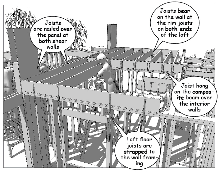
To minimize possible injury, lead carpenters coordinate cutting and framing activities, monitoring the use of saws, nail guns, hoists, ladders, and scaffolding for both the main and upper work areas. For this reason, whenever possible, rim and floor joists are installed from step ladders or rolling scaffolding to reduce the possibility of falling tools, materials, or workers.
Framing Phase – Insitebuilders
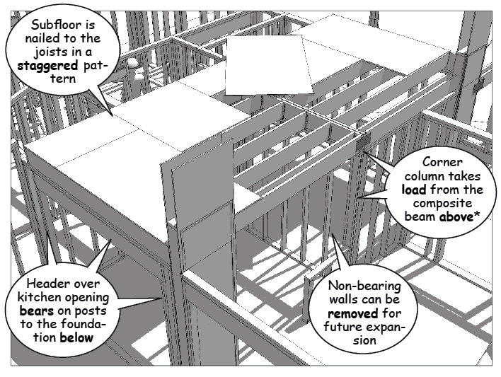
Headers and beams bear on the double top plates of the main floor wall framing and the embedded columns. Once in place, they are secured with clips, straps, or fasteners at the beam pockets, following engineering specifications and local building codes.
Framing Phase – Insitebuilders
Sheathing for the shear walls is nailed continuously across the upper floor framing to maintain lateral resistance within the structural frame. The upper floor joists are then placed to “sandwich” the vertical shear wall into the floor framing before the subfloor is installed.  

Framing the entry roof 
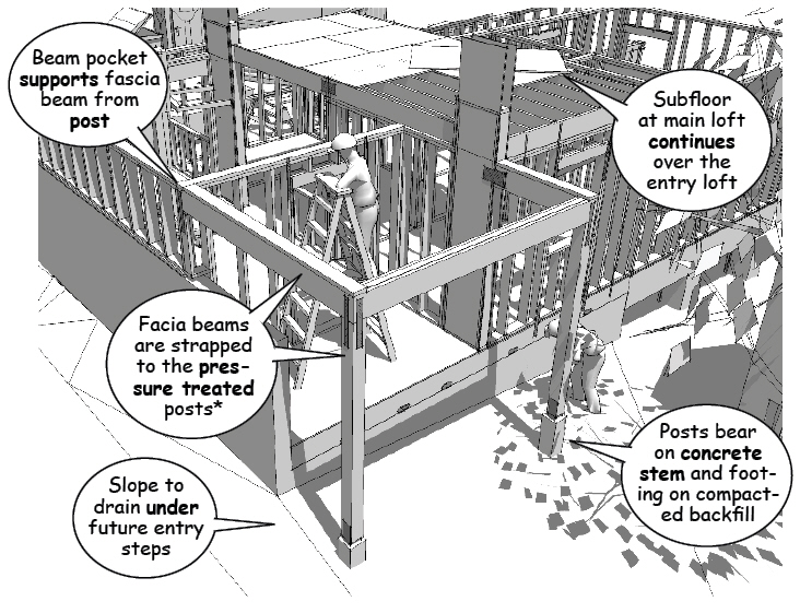
Structural connections require special attention when freestanding roofs extend over open areas beyond the plane of exterior shear walls. For example, in this tutorial the entry roof is open on three sides and exposed to lateral and uplift loads. This leaves the framing vulnerable to the environment, loads from wind, earthquake, rain, snow and insect damage.
Framing Phase – Insitebuilders
This exposure also makes it important to install the framing members using tie down straps, as well as post footings with base brackets that compensate for uplift and moisture penetration. Engineered structural connectors are again required by building codes in most jurisdictions (See Simpson Strongtie).
Framing Phase – Insitebuilders
Before the sheathing is finalized, carpenters add blocking between the floor joists to stiffen the frame at center span and bearing positions. Solid blocking is installed at post or column bearing points to carry loads through the upper floor framing to the foundation or girder beam below.    


(To be continued…) 
---------------------------  

The material presented in this series has been taken from our book, “How a House is Built: With 3D Construction Models” The book includes annotated illustrations, captioned text, videos, models, and the 2D Preliminaries. 
 Insitebuilders.com