Saturday, December 27, 2008

3D Construction Model Controls Engineering Information


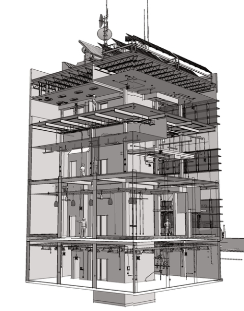
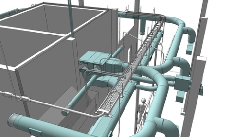
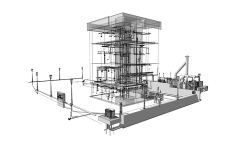
The construction model for this steel stair tower was built piece by piece right down to the bolts and connectors. It is 41 ft tall and will provide access a large cooling tower here in Monterrey, Mexico. Except for the critical dimensions, elevations from grade, and the general layout, the stair was built directly as a three dimensional model. This means we did not need to invest a lot of time with two-dimensional engineering drawings.


This is important because the model is to be used to illustrate a preliminary proposal for design and construction and is the basis for a cost proposal for the project. Because it is a 3D construction model, we are able to control our initial engineering assumptions and the structural details for the project and at the same time provide our clients with enough visual information to understand our concept. In other words we were able to be competitive without “giving away” the steel profiles, connection details, and 2D drafted documents and structural details that may have been lost from our control.


Once the project has been accepted, we can export the model into our CAD progeam to generate the 2D drawings directly from the model. This means final approval will be very quick and we can move immediately into fabrication and final installation. Important is that the construction model is available to support the entire process and can be continually viewed for clarification and visualization. This will of course simplify fabrication and be helpful to our office for fine tuning our calculations, the 2D drafting, and do the structural detailing for the connections.


The value of a construction model is that it gives us the ability to manage our commitment to the project, control the information we provide to our clients, and use the resulting model to facilitate the design and construction process.


Joel Kennington

jdkennington@gmail.com

Monterrey, Mexico


Monday, November 24, 2008

4D Modeling and Scheduling Software for Google Sketchup.


Project managers face a unique challenge in construction planning because they have to calculate the most efficient and cost effective way to build a design, while clearly communicating the construction process to clients and other stakeholders.


Recently, project managers have adopted 3D modeling and 4D scheduling programs to help in this critical phase of the construction project.
4D modeling combines 3D drawings with a construction schedule and displays the sequence of construction over time.

Syncro has developed a plugin for Google SketchUp along with their full line of 4D systems for various sizes and types of construction management teams. Synchro has been developing innovative scheduling systems since their start in construction software 2001. Syncro’s software integrates models from popular CAD programs like Google SketchUp, as well as Revit and Auto CAD, and then synchronizes them with a project timeline on a spreadsheet. The result is both a visual and spatial representation of construction as it occurs through time.

This innovative new 4D plug-in for SketchUp was introduced at the 2008 CMAA conference in San Francisco and Software Advice, an online resource that helps construction companies find construction management software, was there to capture the importance of Syncro’s new 4D tools.

Their video of the plug-in can be seen below or on the Software Advice website.


The viability of 4D modeling software as an effective planning tool has prompted much discussion among leading construction professionals. So much so, that Stanford University’s Department of Civil Engineering held their own research study. Their study reveals that project managers and stakeholders can indeed understand a construction schedule more quickly and completely with a 4D visualization.

In a real world scenario, 3D and 4D construction modeling software has definite advantages. Construction projects are complex, and modeling software helps project managers anticipate and plan for delays and miscalculations. Now 3D construction modelers can use SketchUp to track their projects in 4D !!

(Submitted by Houston Neal, Software Advice)


Sunday, October 19, 2008

Piece-Based Construction Models


Graphic communication in design and construction is nothing new. It has long included the traditional 2D and 3D drawings found on every jobsite. In an increasingly competitive economy, constructors have even begun to regularly use new tools such as animated slide shows, illustrated word documents, and simple sequence animations to differentiate themselves from the crowd.

In fact, the videos and tutorials included with our books are now used by architecture and construction schools all over the world to illustrate classroom handouts, lectures, websites, and student projects. At the same time, many professional developers and contractors use these learning aids to support their ideas and illustrate their own construction methods and practices.

It’s no secret then that in order to survive we all look for every available tool to quickly communicate complex ideas with our clients, manage risks, plan and document our projects, and clearly explain project methods to a broad community of interests. This might explain some of the interest in the building information models (BIM) that are just beginning to reach the mainstream of the construction industry.

There’s little doubt that this new environment of graphically competitive practices makes 3D construction models even more important for the future. Construction models are piece-based because they are organized so that every part of the model can be easily identified, modified, and reused in another model as a distinct three-dimensional object. These objects are then counted, measured, and categorized so that their data can be used to graphically manage estimates, schedules, and other related projects.

Each of our books includes all of the piece-based construction models used to illustrate that book. This means that each book is a three-dimensional library of not only the parts and pieces of the constructions, but also a collection of the furnishings, tools, equipment, and workers used in the virtual model. Readers are therefore free to deconstruct, reconstruct, and visually explore their own ideas whether in a classroom or the real-world. The notion of shared three-dimensional resources in a virtual model is one of the underlying goals of our books.

Wednesday, September 17, 2008

Construction Modeling Method


3D construction models begin with a set of 2D contract documents. These are the construction documents that represent the scope of the contract requirements provided by the design team. The model is constructed to confirm a bid, during contract negotiations, and in the field just ahead of the actual work.

The idea is to use the 3D modeler as a tool to systematically check the 2D documents, test details and dimensions, and understand the assumptions made by the design team -- before the documents are used in the field.


Start with a site model: this is a scaled scan of the plat map or survey laid over a geographically accurate model base. Use the site model for site utilization planning (SUP), to simulate the impact of weather and sun on construction activities, and to map the regional context of the jobsite.

Excavate the building from a workpoint. Base cuts, grading, and shoring on the referenced elevations and dimensions shown on the survey and plot plans. Use scaled equipment models to test available access routes, stockpiles, and staging.

Use the 2D documents to begin the foundations (formwork). Set up the scaffolding, falsework, and equipment that will be needed to complete the foundation. Include reinforcing, connectors, and other specialty items shown on the contract documents. The modeling program automatically surveys quantities and identifies phases, tasks, and errors and omissions.

Build the structural frame according to the engineered documents. Include staging and lay down area as well as scaled models of the workers, tools, and equipment necessary to complete the framing. The model is built using the sequence and processes anticipated for the construction. Survey quantities are again automatically generated, means and methods are coordinated with field teams, and the resulting model illustrates areas of concern, RFIs, and conflicts.


Building systems are installed per plans and specs.
Important is to build these systems in the order of their actual construction using scaled models of the tools and equipment needed by each subcontractor. Sequence modeling highlights conflicts, anticipates coordination problems, and tests design assumptions.

Finish work follows the contract details. 3D component models are fitted to roofing, curtain and window walls, siding, finishes, cabinetry and furnishings. The completed model focuses on coordinating processes and sequences necessary to complete the contract obligations.

The result is a construction model that details the means, methods, and processes represented in the contract documents. Errors and omissions are identified (often output from a poorly constructed BIM model) and schedule concerns, subcontractor challenges, value engineer alternatives, and real-world conflicts are illustrated for all to see in three-dimensions.

Monday, September 1, 2008

SketchUp as a Construction Modeler

One thing to keep in mind is that a construction model is not the same as a building information model (BIM). A construction model graphically communicates the means, methods, and processes found in the production of complex objects. It dynamically represents the sequence of events necessary to build that object.

Our books demonstrate the potential of construction models and their ability to graphically communicate construction processes. First using an early versions of AutoCAD (Graphic Communications in Construction, Prentice Hall), then exploring the potential of web-based visual systems (The Web @ Work, Homebuilder Press) and most recently as a series a graphic narratives using SketchUp as a construction modeler.

The potential of SketchUp for construction management was first explored at the University of Florida in 2001. SketchUp was used to quickly orient construction management students struggling to learn how to build piece-based models with AutoCAD 2000.

That early effort evolved into an advanced construction modeling class and the first book, 3D Construction Modeling: Project Based Learning. This early book broke new ground simply because it was based on the work of several comic and graphic novelists. It used SketchUp V4 to explore the format and delivery of construction information on the two dimensional pages of a book. The models are dated, but the book remains popular as a project-based learning tool.

Our next book, Living SMALL:The Life of Small Houses, expanded on the lessons learned from both SketchUp and publishing a graphic narrative. Living SMALL uses SketchUp to build 16 small houses. The idea was to mix modeling tutorials with video tours of three-dimensional models to convey some of the traditions of home construction and the values of small house construction. The 16 models also tested different organizational structures for the models and hinted at the potential of SketchUp as a construction modeler.

The results can be seen in our next book, Building SIMPLE: Building and Information Model. This book used many of the new features found in SketchUp V5 to explore the organization of a large construction model and communicates the production of a mid-rise office building. The models with this book were the first to be “outlined” with V5’s Outliner feature and the first to communicate real-world construction as a sequence of collaborative events. The models and illustrations from this book are now used internationally to illustrate and explain construction methods.

These values were continued in our next book, Being SUSTAINABLE: Building Systems Performance. Construction models in this book were built using Google SketchUp. The book, models, and video tutorials illustrate the mechanics of sustainability in the same mid-rise office building found in Building SIMPLE. The models push the limits of construction modeling in SketchUp and the real potential of three-dimensional modeling to illustrate complex systems. The value of the book is that it illustrates the collaborative promise of SketchUp and construction modeling to bridge the information gaps often found in the real-world when dealing with complex building systems.

We’ve also used SketchUp to publish assembly manuals, forensic models, and fabrication models for management consultants, contractors, and manufacturers and are working on a new book using SketchUp to illustrate every detail in the construction of a wood frame house, How a House is Built: With 3D Construction Models. This book is also an updated project-based learning tool on how-to-build construction models with SketchUp.

The goal is to improve construction communications. The objective is to make complex construction information quick to read and easy to understand. With these books, we’ve found that very complex construction models can be built using a simple three-dimensional construction modeler called SketchUp. And the best thing about SketchUp is that it is free.

Saturday, August 2, 2008

Reprint of 3D Construction Modeling

Classic book using SketchUp for construction modeling

3D Construction Modeling

Do to many requests, we’re reprinting the book 3D Construction Modeling and distributing it to booksellers and offering it again on Amazon. The book includes a trial version of SketchUp V4, which is a much simpler and basic program than Google SketchUp.

V4 has black and white icons, V5 has color (and new icon shapes) and an organizer called the Outliner. The Google SketchUp version adds a bunch more stuff like Layout, performances, sketchy edges, warehouse imports, photo match, etc. All design features that are not always necessary for most construction models. At least we never use them.

The book covers the fundamentals of building a piece-based construction model using the tools you find in all versions of SketchUp, but does not go beyond what is necessary to plan, layout, and build a construction model. This includes site planning and site layout modeling and subsequent chapters on how to fabricate and install the pieces of a wood frame building (and take them apart). There is also a chapter on shade and shadow, animation, and other simple effects in SketchUp.

The value of this book is that it introduces the reader to the basics of construction modeling using this simpler version of SketchUp — making the transition to the current version easier. It remains popular because it helps readers understand the piece-based concept of assembly and production modeling.

We are publishing a companion to this book later this year titled “How a House is Built.” The new book is not an upgrade in that it will not be a step–by-step hands-on learning experience like this one. But it will show how both a house and a construction model of the house are built using Google SketchUp, including mechanical, electrical, and plumbing as well as a “How To” page with video demonstrations rather than tutorials.

For more information about our construction books, see http://insitebuilders.com


Revit vs ACAD


We’re sharing this email for those considering alternative 3D construction modeling programs. It’s a direct cut and paste from an email response to Abdol Chini, Director, Rinker School of Building Construction, Univ of Florida and since it is just Dennis’s humble opinion, comments are welcome.

Abdol:

IMHO Revit is the wrong direction for a const school — tho it makes great sense as a draftg tool in an arch school b/c 3D models are para-linkd to 2D dwgs — by the *design professional* (arch/engr not constructors).

The problems I see:

1. Revit is a draftg prog. This makes it important to compare apples to apples. IOW, is the goal draftg?? Or modelg?? Or construction?? ACADs strength is that it is both a 2D drafter and a very advanced 3D modeler. Tho slowly antiquated as a drafting prog, most do not see ACAD as the underlying 3D modeler. For ex, I can remember when Prin, Mark and I went to Haskell to demo Prin’s research (I think in ‘99), there was an audible gasp from the drafters and architects when we spun a 2D dwg in 3D. IOW, they never used the ACAD 3D environ other than to draft in 2D. Which is why it is no longer a viable prog.

This is important because the 3D models extracted by Revit and many other programs use the same modeling engine powerg ACAD today. We (Rinker) began using the early version of this engine to build what are now called BIMs when it was first released in R14 (1997/8…wow, long time ago). In sum, Revit is the 2D component of the underlying 3D software system, it extracts 2D docs from 3D models (parametrically). Is that what you want?

2. Upgrade req’d to graphic workstations. There’re only a few good laptops (DELL M90/+ Precision Workstation or G6) that can run Revit once the models and linkd dwgs go beyond a simple bldg (file size). Using Revit would mean a big commitment by both the school, faculty, and students to purchase high-end graphic workstations (and learn to use them). My M90 cost $4100, and our now-belo-avg-graphic-desktop workstation came to around $6500 — the money is in upgrading a std platform with faster graphic cards, memory, and monitors. Revit will run on lesser machines, but not for long…as complexity increases.

3. Question the value of “BIM” to construction managers. Few construction students I know (knew..) would be interested or motivated enough (let alone faculty) to learn Revit, especially in a single 3unit semester/year. It is a deeply complex prog and will take a long time to master — and I’m not sure to what purpose (for a CM)? Perhaps thgs have changd at Rinker, but I found students only wanted to know what they needed to know to be effective CM/PMs and had no interest in draftg.

4. Very steep learng curve. Even with the simplified versions we used at Rinker 12 years ago, modelg was a challenge. We did great work and many “ex” students still jokingly email about the models we built in those early days of ACAD R14/2000/i, but we also tortured a lot men and women who had no interest in understdg how to model (let alone draft…) in ACAD or any other prog. Pushg a class up that learng curve would miss the real value in BIMs and how they can be used as true const info models (which differ from BIMs).

5. Revit’s not the best pro-BIM modeler, just the easiest. If the goal is to teach a gen of RW const modelers (instead of const mgrs), I would highly recommend CATIA, Bentley, or SolidWorks. These are the higher end and much more capable BIM modelers b/c they match CAD/CAM fabrication — though the 4 probs outlined above are amplified by their increased comp power. These are the RW BIM modelers used by design/const pros (Ghery, Martin, Denver MOMA, ConX come to mind), most of the other offices (and schools) are casting around the low end tryg to figure it out. IMHO…)

6. BIM is not about 3D. BIM is about automatg info relationships using piece-based const models. For the const managers this means modelg both process and sequence as well as volume and sq footage. IOW, the significance of const modelg is to use a modelg prog as a “tool” in order to communicate values — cost, schedule, SUP, green, whatever…not to auto-gen a 2D doc (which I should note does not really work in the RW…IMHO…). A 3D modeler is no more than a sprdsht or scheduling prog….its a comm tool. For ex, we used this as the strategy for the D-B teams way back when and why those students were able to compete effectively with other schools at both reg/national levels — they were able to visually animate their ideas…..(BTW, how are the teams doing??)

This is also what we used to teach in BCN4301 (you may remember the color prints of the student exhibit in 2003 were slides from Ppt presentations. Also note about half of the models displayed in that exhibit were senior projs, using so-called BIMs a lot like they were/are being used in the industry (today) — to communicate ideas. Many of those students are now instrumental in introducing the tech in their companies…

There’s probably more but basically I would recommend keepg it simple and tryg to move 3D into and across the curriculum as a communications tool and not lose focus on the importance of 3D as a tool to visually (graphically) manage/transfer ideas and info. There are several progs offering this capability, but Google SketchUp is the one that seems to be catching on universally. Primarily b/c its free…and its Google.

The trick to using SkUp as a construction modeler is to make it work object-oriented. Only a few construction schools (but many contractors) have picked up on this capability b/c it takes a little longer to make it work and means using a little known/used element of the prog called the “Outliner” (ref my books, especially the recent one on MEP systems…) http://insitebuilders.com

You might consider: 1) intro SkUp in 1252, use it to teach hands-on 2D (IOW build simple BIMs in 3D from 2D docs), 2) move to const info modelg/graphic comm in 3255 with Ppt/seq animations/SUPs/etc linkg BIMs to illustrate other coursework, and 3) use BCN4301 to teach ACAD-3D and Revit (tho not sure who’d take it??..;-). 4) A better idea might be to use 4301 to integrate senior projs as a kind of competitive marketg class and force students to visually explain the values of their projs is 3D….(again IMHO)

Wednesday, July 2, 2008

BIM: Promise and Potential


The Promise

With the promise of Building Information Models (BIMs) becoming increasingly important in both the design and construction of engineered structures, it might be a good time to step back and take a realistic look at the real potential of these new technologies for our industry.

In fact, this technology has such a strong visual presence it’s hard sometimes to separate the promise from real potential. Take for example the underlying responsibility for the information transferred in one of these models. Disclaimed and often undisclosed, few designers are ready to assume liability for either the model or the information it might (or might not) contain beyond the resulting collection of contract documents.

In other words, though spatial data, net area and efficiency ratios, program compliance, and energy performance might be extracted as information from a BIM model, it continues to be the responsibility of the contractor to cross check and verify any contractually relevant information represented in the computer generated data. That means the “I” in BIM is just that, information, and much more of it.

The Potential

This is clearly evident in recent discussions among design professionals working to incorporate BIM models into the production of construction documents. Here in fact is where BIMs have their real potential.

The dream is to use software and computers to seamlessly transfer a design model into a set of construction documents. This can be accomplished in two ways. The simplest method is to graphically export two-dimensional images of the three-dimensional model into a CAD drafting program where they can be scaled, dimensioned, and annotated as part of a set of construction documents.

However, by definition the goal is to use more complex programs to parametrically link the model with a two-dimensional drafting program so that any change to the three-dimensional model is automatically reflected in a two-dimensional drawing (and vice versa). In fact, according to the General Services Administration (GSA), without this parametric intelligence it is not a true building information modeling.

Interestingly, both the design professionals and construction managers are expected to use these models to produce shop drawings, field drawings, estimates, and schedules. This of course blurs the line of liability issues under a one-for-all-and-all-for-one approach to project development and cast the shadow of an even more litigious project life-cycle for both designers and constructors.

Automated information

What we are beginning to see as a result is the automated production of a collection of two-dimensional drawings, reports, and volumes of specifications, all automatically generated by a computer. Every bit of this information must then be verified just like any other set of construction documents, except it is now camouflaged by the constantly increasing ability to generate more documents, quantitative reports, and graphic information than ever before.

The result is that this great new BIM potential for engineers and architects leaves construction professionals on the receiving end of a fire hose of automated and unverified data with few options and no equivalent three-dimensional tool with which to respond.

Of course, some construction companies are able to tap into these innovations by training and hiring more technically inclined constructors and putting them to work either closely coordinating the production of the three-dimensional models or developing an in-house modeling department.

However, the implications of this level of integrated and collaborative approach are again shadowed by the responsibility for the resulting information -- essentially moving the construction professional wherever possible into a role of monitoring the production and accuracy of the design model in order to understand the underlying basis for the final contract documents. And that’s assuming both the modeling and construction expertise of the construction manager fit the scale of the project.

The Real World

In reality, every one in the industry knows that it’s very rare for a project of any complexity to evolve in a systematic and orderly fashion. Clients are often faced with dynamic market conditions that mean adjustments must be accommodated not only through document production, but often onto the jobsite.

At the same time, design professions deal with an ever increasing array of new materials and methods. The challenge is to coordinate and incorporate these new technologies into details and documents that must support a carefully negotiated legal contract.

The resulting process may appear to academics (like me) as a wonderful occasion for what the GSA calls an open and transparent “integrated spatial program.” And there is no doubt that it is, but the reality of competitive pricing, materials shortages and the cost of doing business, and regulated complexity of a jobsite make it no more than a dream in the real world of the mainstream construction company.

What constructors need is a corresponding modeling tool. BIM for the contractor is not about spatial relationships, visualization, or building performance. It’s about intelligently and dynamically automating the daily challenges of the construction contract. What are required are construction models.


Construction models

A construction model differs from a design model for three fundamental reasons. First the model must be piece-based. Not just object oriented, but virtually definable in components that make real sense on a jobsite. To a contractor information goes far beyond unit counts and much more deeply into piece-based relationships of fabrication and assembly. This makes the number of bolts or windows in a building immaterial when considered in the context of their installation during real world project production.

In the field, this means information must be available on the fly, day-to-day and hour-by-hour, intuitively variable. A construction model must be fast, flexible, and feasible. Simple to build, change, and manipulate and accurate enough to visually test or illustrate a field operation.

Second the model must be able to capture the process and sequence of multiple operations. In other words, the model must be able to go far beyond simplistic 4D phasing. Construction models are organized according to a detailed and robust work breakdown structure. They must of course include time, but they must also include the variables and alternatives that come from frequently changing schedules that almost never seem to follow the original plan.

Finally, a construction model must capture both the means and methods of a construction. This includes all the tools, machines, equipment, scaffolding, and falsework necessary to complete the project according to the contract documents. These are clearly critical elements of the construction process that are not shown in a BIM model, included in the specification, or parametrically linked to two-dimensional drawings.

Fast, flexible and visual

It’s important for constructors to recognize the difference between these two radically different approaches to intelligent modeling systems. A BIM model is a (hopefully) realistic representation of the project. Its value to a designer is that it will (hopefully) automatically generate a set of construction documents. Its value to the client is that it (hopefully) accurately represents spatial and performance values in that design. But its value to the construction professional is that it only takes a small step toward the broader and more complex issues that will face its construction.

Who?

Dennis Fukai, Architect, PhD

http://insitebuilders.com/CV
-----------------

Dennis is a licensed architect and construction manager with more than thirty years experience as a professional construction administrator, researcher, and construction management professor. He is a Fulbright Scholar and earned his PhD in architecture from the University of California, Berkeley. Dennis has written seven books and numerous chapters and articles on graphic communications in construction and has been recognized internationally for his work in advanced construction modeling and information systems. (See http://insitebuilders.com/CV for more information)

---------------