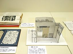
These were very early multidimensional construction documents, viewed as a series of pages in a set of 2D working drawings and at the same time folded into three-dimensional construction models in order to visually communicate the details of the completed building.
Two dimensions of 3D
In a modern interpretation of the okoshi-ezu, simple 3D modeling programs of the 21st C can and are being used by a generation of technically oriented constructors to capture 2D and 3D images that can be quickly added to purchase orders as a shop drawing, or as a diagram of a solution in a RFQ, field bulletin, or change order.
The trick to drawing with any 3D modeling program space is to keep in mind that a 2D drawing is nothing more than a collection of lines, notes, and dimensions on any two-dimensional plane in the three-dimensional environment.
http://insitebuilders.com/Blog110715/02-InTheMachine3d.jpeg
All one has to do is orient the drawing to a fixed and flat point of view -- anywhere in the construction model.
Drawing on a 2D plane
For example, in a program like SketchUp, select Parallel Projection in the Camera menu to flatten the image and eliminate perspective, then use the Camera menu to select one of the standard top or side views.
Next, pan and zoom your view point to an open space somewhere in or on the model that’s large enough for the image you want to draw. Once the location is set, use the Scenes dialog box to add and name it as a Scene.
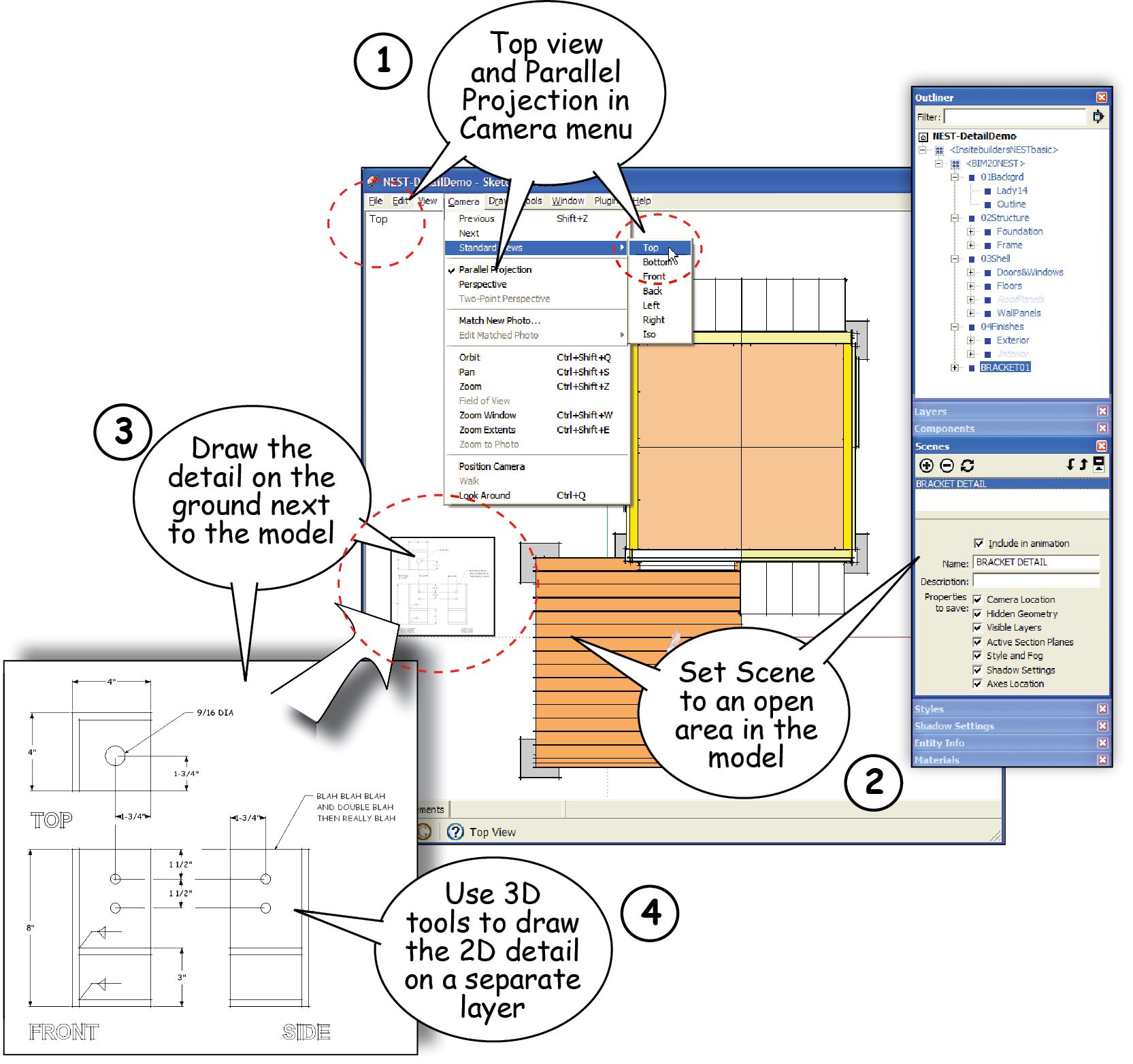
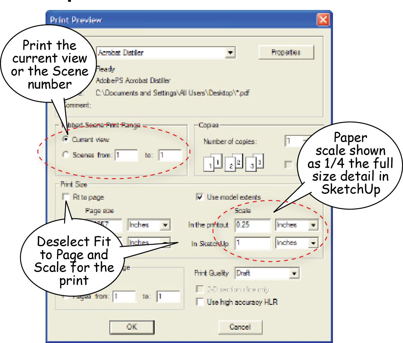
Now all that remains is to use the Line, Oval, and Text tools along with inferences and guidelines, to draft the detail on the two-dimensional surface. Since the drawing is literally built at full size, there’s no need for rulers and scale calculations. Printed scales are controlled by the SketchUp program in the Print dialog box.
2D from a 3D construction model
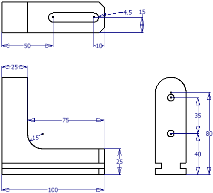
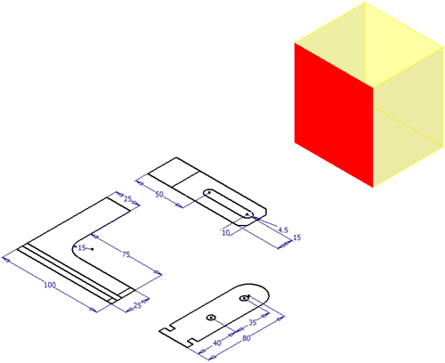
A 3D construction model can also be used to capture two-dimensional plans, elevations, and sections.
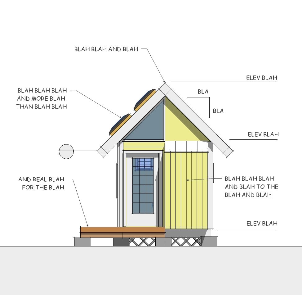
2D Elevations
To do this, keep in mind that 2D building elevations are no more than parallel projections of one of the standard views around the outside (or inside) of the model.
To capture these projections, use the Camera menu again to position a preset standard view. Select Parallel Projections. Then adjust the shade and shadow controls to add depth. Shade and shadow might also be turned off completely to eliminate shading that might be distracting.
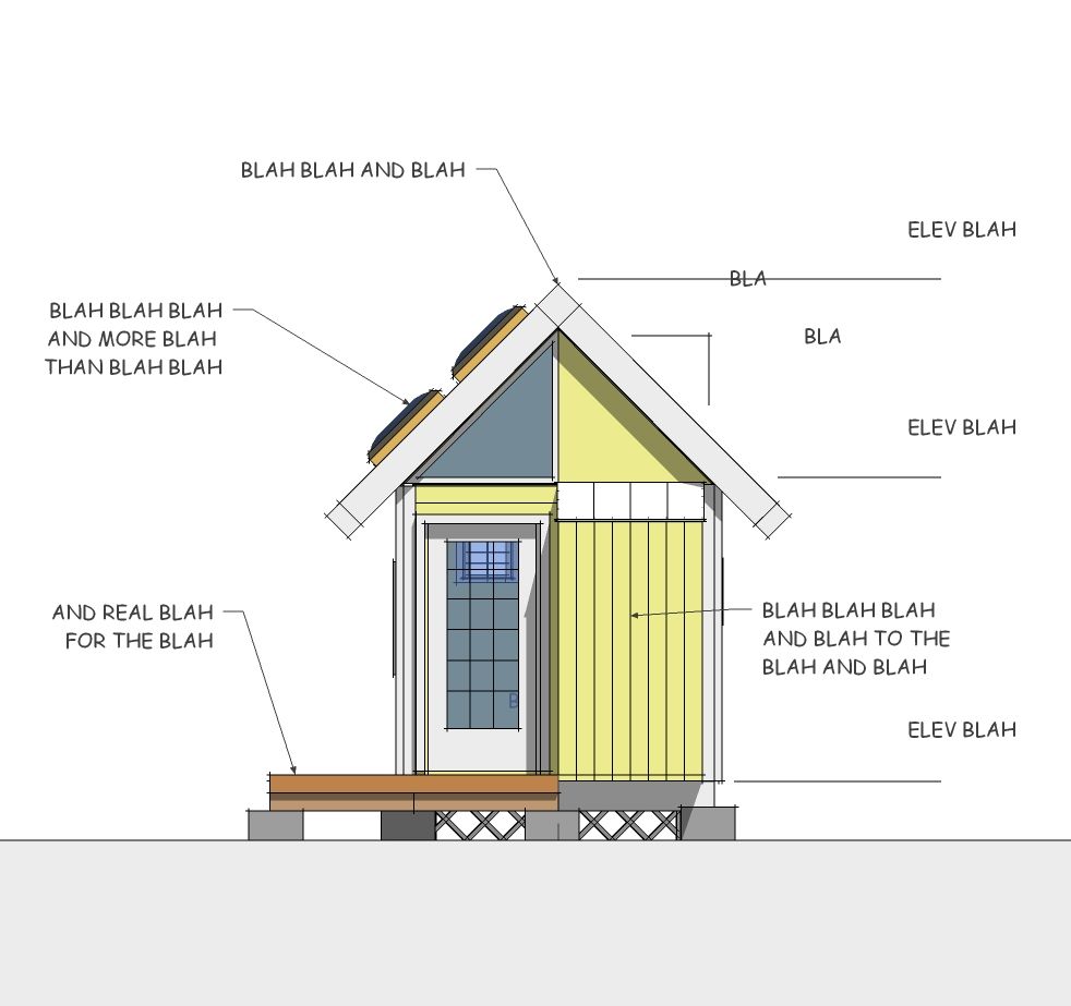
Once the image is ready, notes, projection lines, and dimensions are added and grouped on a common layer so that their visibility can be controlled or hidden with the Scene’s specific properties. The size of the model in the display is again not important since scaling will be calculated in the Print dialog box.
2D Floor Plan
Use the same technique to cut horizontal sections through the model as 2D floor plans. Start by selecting the Parallel Projection and the standard Top View settings in the Camera menu. Place the section plane through the window’s waist line with the Section tool so that it includes the wall openings.
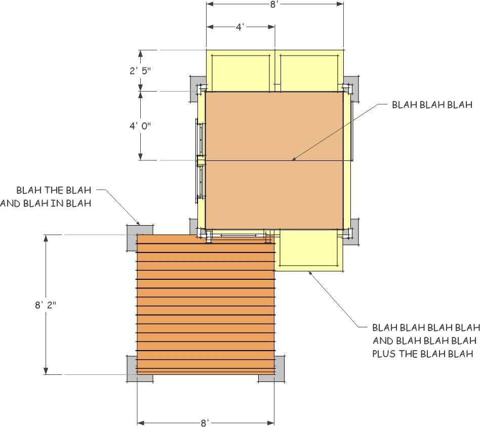
Zoom and Pan to set the Camera’s point of view for the floor plan, then annotate and dimension the plan on a separate layer, or group in the Outliner, in order to control their visibility from scene to scene. Finally, click to add and name the floor plan in the Scene dialog box, making sure to set Scene Properties so that notes and dimensions are only visible in this one scene.
2D Building Sections
Cutting a vertical section is a lot like cutting a cake. In SketchUp you can extract a 2D outline of the profile of the cut at the section plane, but it’s far better to contextualize the section by keeping objects beyond the plane in place to add depth to the two-dimensional view. In SketchUp you can also add shade and shadow, along with Fog and Edge Style and Depth Cue to strengthen the image and adjust the section’s profile – but it’s really not necessary for a working drawing.
3D in 2D
The result of these simple 2d tricks is a collection of drawings as a series of two dimensional scenes. Each scene can then be printed to scale as a single plate or a page in a set of construction drawings. The scenes can also be exported as low-resolution 2D graphics to be cut and pasted into a memorandum, field document, or as part of a larger sheet in a Draw program.
The scenes could even be reassembled and folded into a three-dimensional model – just like an okoshei-ezu.
------
If you’re interested, most of these techniques are detailed in our books on construction modeling. See especially, Mastering the Art of 3D Construction Modeling, 2011.
For an introduction to SketchUp, see the tutorials and forums at SketchUcation.com
You Tube links: Setting up Scenes, Cutting Sections, Exporting 2D Graphics.
.
