Specialty contractors use reusable forms for their foundations, but for most small projects almost any skilled carpenter can quickly layout and assemble the formwork for a foundation footing.
In this example, the footing formwork is assembled with standard lumber that will be reused in the floor and wall framing illustrated later in Phase 4.
Pier work
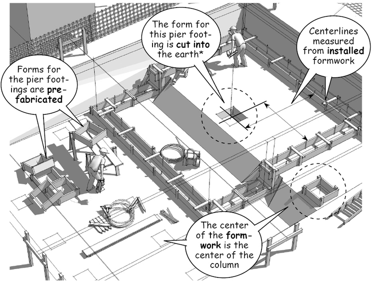
If soil conditions are right, the footings can also be cut directly into the soil as shown for the pier footing on the excavated shelf in the illustration above.
Forms for the rest of the pier footings are prefabricated on site so that they can be centered on the string line intersections marking the column locations, or positioned with a tape measure from the perimeter formwork. The center of the pier footing is the center of the column load coming from above.
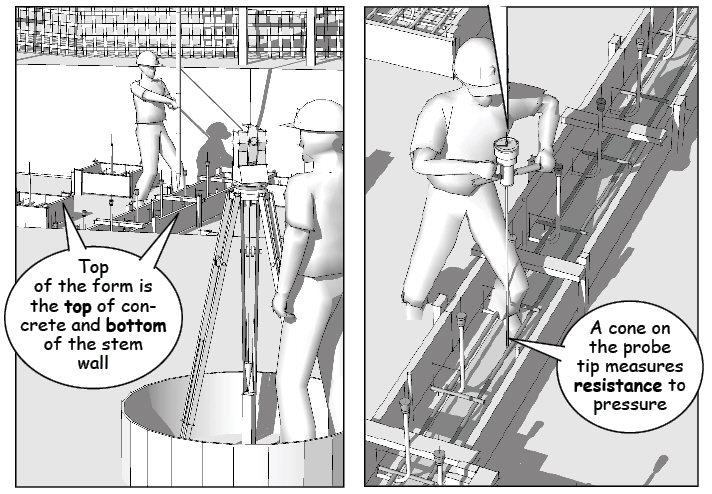
Bridging is used to locate and suspend the concrete reinforcing (rebar) across the top of the open earthen formwork, or from the sides of the prefabricated forms.
For heavily reinforced foundations, some contractors prefer to use light weight plastic “chairs” to hold the rebar up off the floor of the excavation (See Craig’s Concrete Specialties). The size and location of the reinforcing varies with soil conditions and the weight to be distributed over the undisturbed surface of the excavation.
Quality control
It’s important to check the location and elevations of the footings for accuracy, as well as test soil density to make sure it meets the original engineering specifications. Loose or disturbed soil will sink or compress under the weight of the building.
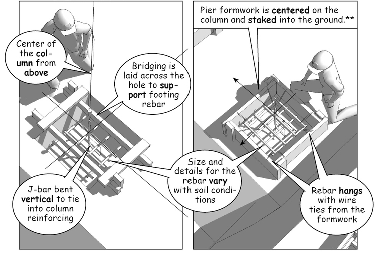
Depending on building type and local conditions, some building departments will require certification for the location of the footing, along with penetration test results verifying soil density before authorizing concrete placement.
The workpoint is again the primary reference to check the layout and vertical elevations of the footings. It’s easy to see how a level and accurate excavation minimizes unforeseen material and labor costs for all future construction.
Continuous reinforcing
Standard lengths for rebar are 20 feet, with diameters measured according to increments of 1/8”. In other words, a #4 bar is 4/8” and a #5 bar 5/8”. This means the rebar must be cut and bent in the field to fit in the formwork using a hydraulic tool (similar to this one supplied by Southern Tool).
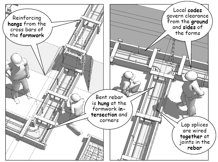
Crossbars are installed to keep the formwork rigid and suspend the rebar. The steel reinforcing is tied to keep it away from the sides of the formwork and up off the ground. Again, chairs or similar spacers may be easier for some builders to install.
Clearances from the ground and sides of the formwork are necessary to protect the rebar and distribute the loads on the foundation once the concrete has cured.
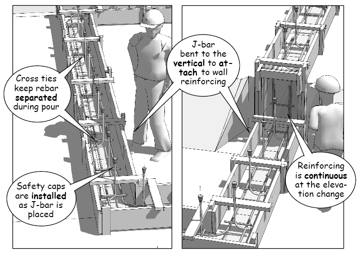
The rebar must also be continuous at all intersections and around corners because any gap or break in the length may result in settlement cracking once the footing is under load.
Special attention is also required at any step or change in the footing elevation. Concrete stem walls are formed to fit this step, but for a masonry stem wall, the step should be located so that it fits standard masonry dimensions.
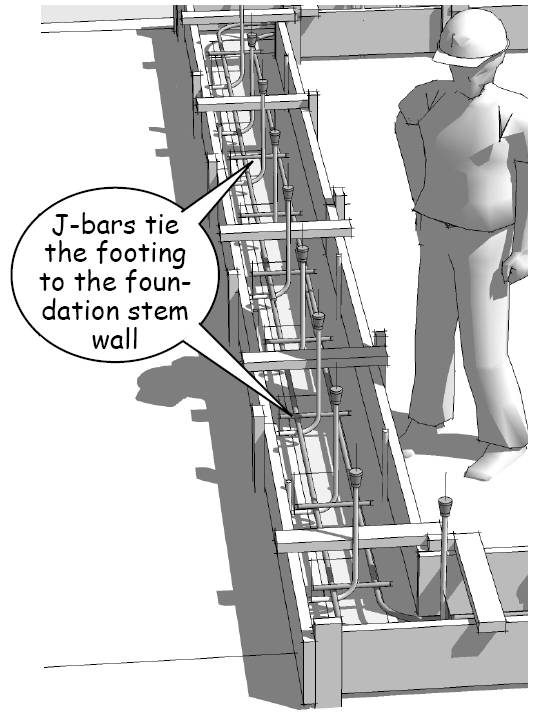
As you’ll see in a later phase, the stem walls require embedded vertical J-bars to tie reinforcing within the wall to the footing after the concrete is ready for the next step in the foundation’s construction.
.
.(To be continued…)
---------------------------
The material presented in this series has been taken from our book, “How a House is Built: With 3D Construction Models” The book includes annotated illustrations, captioned text, videos, models, and the 2D Preliminaries.

www.insitebuilders.com
.
